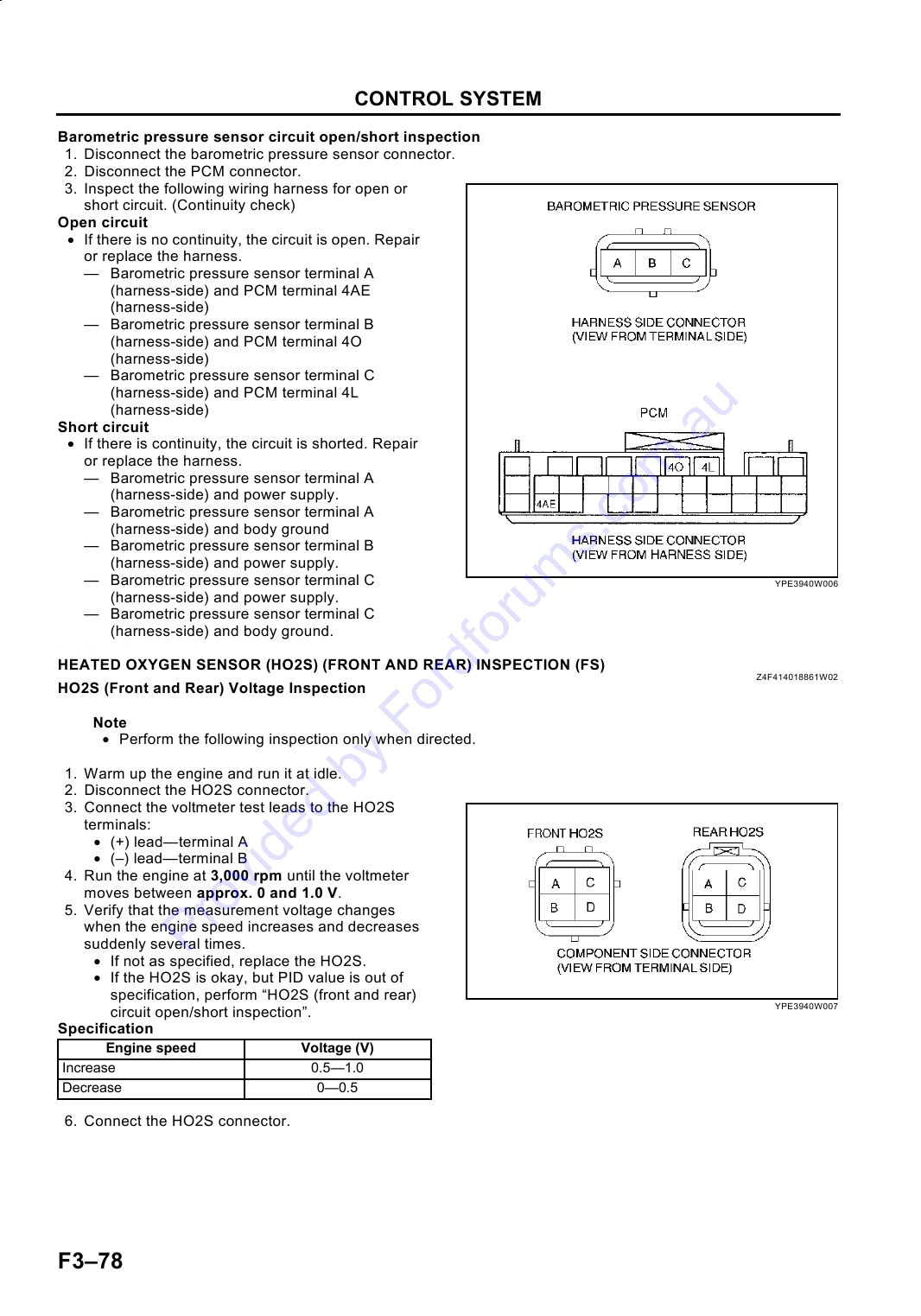
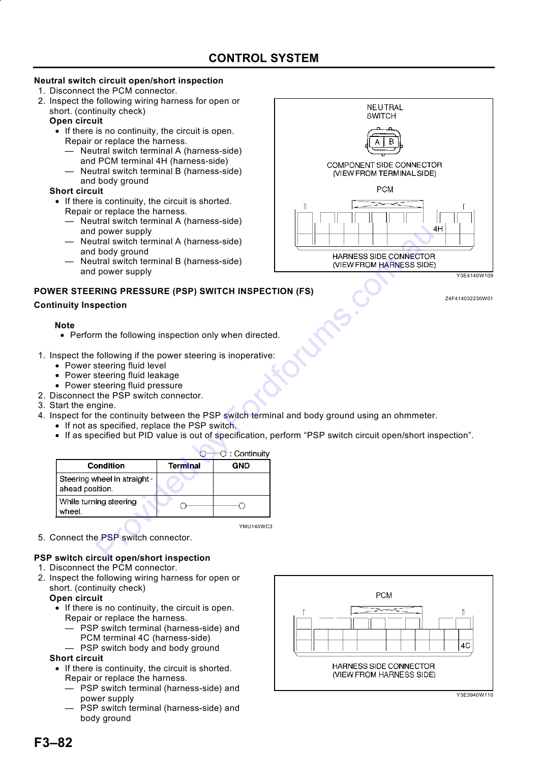
FUEL AND EMISSION CONTROL SYSTEMS
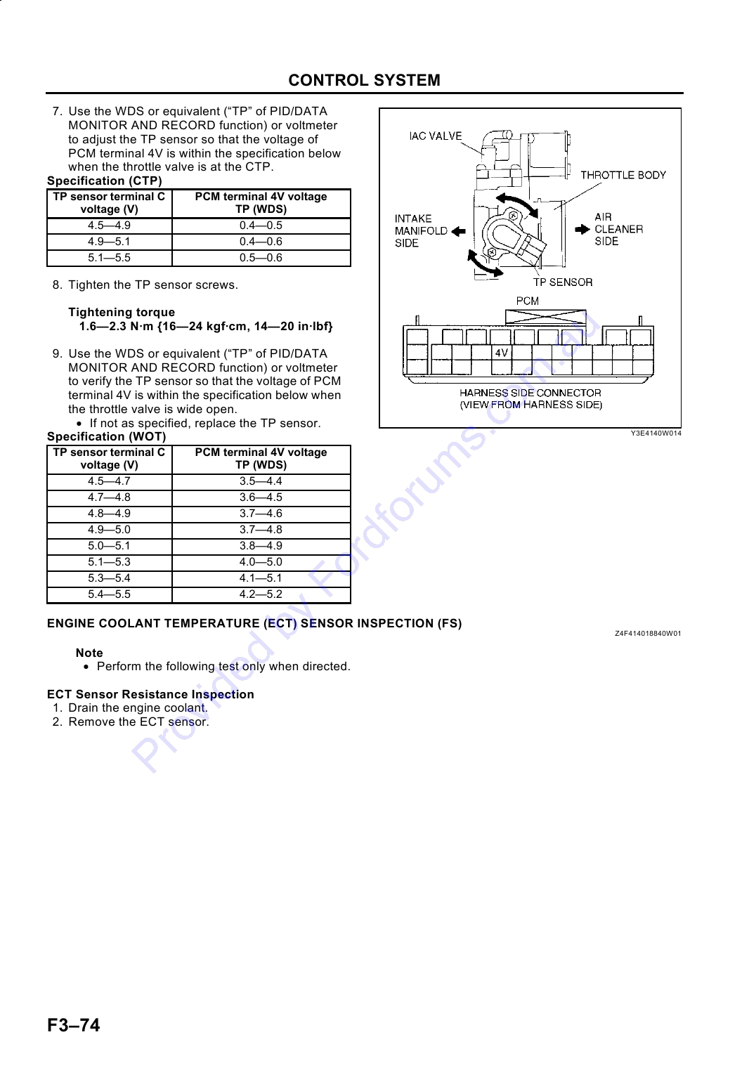
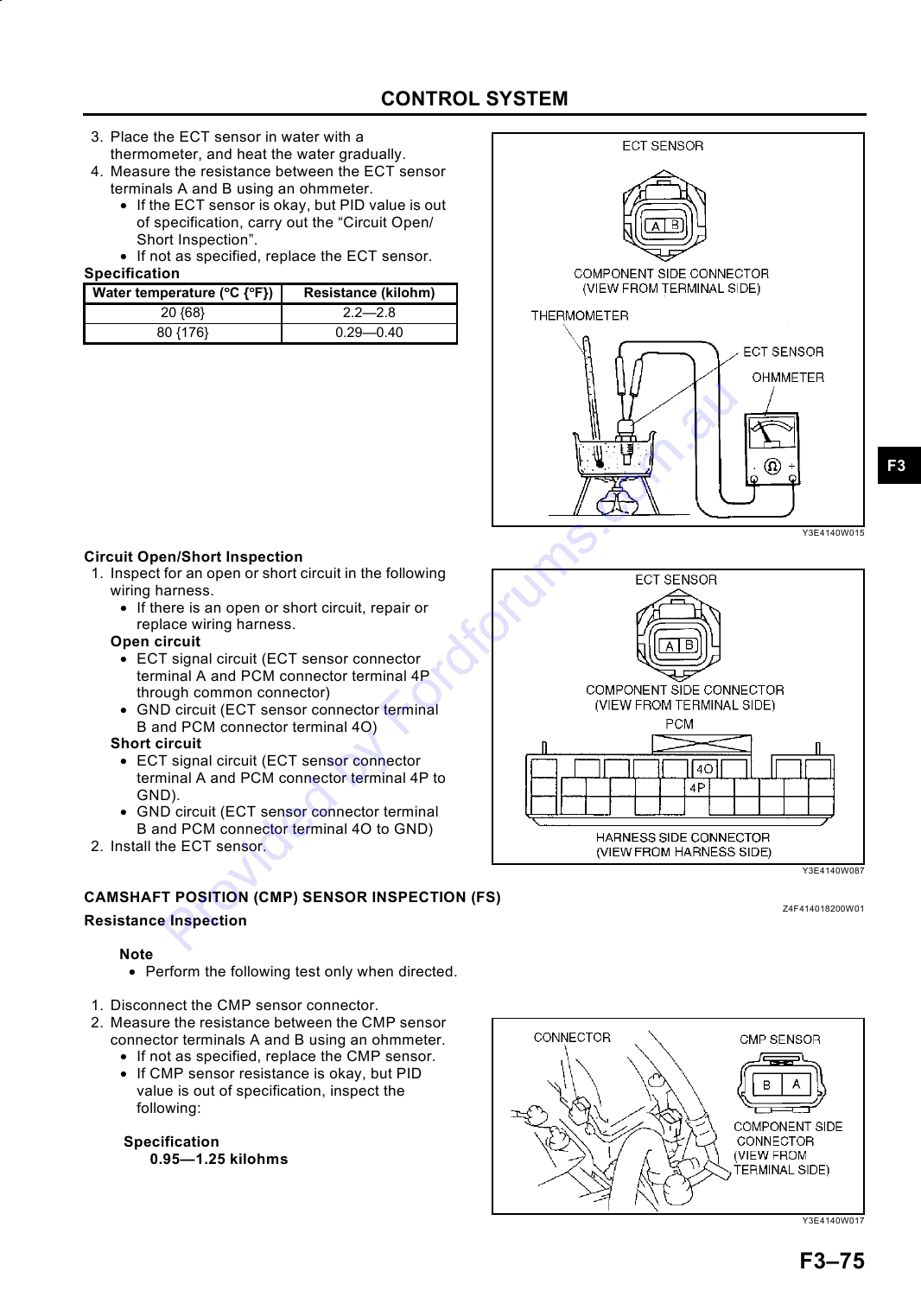
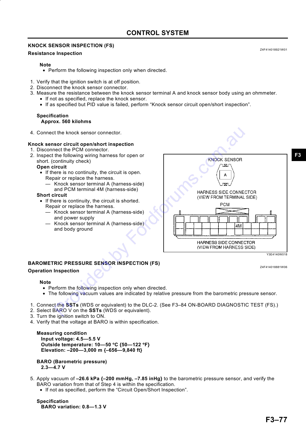
F3
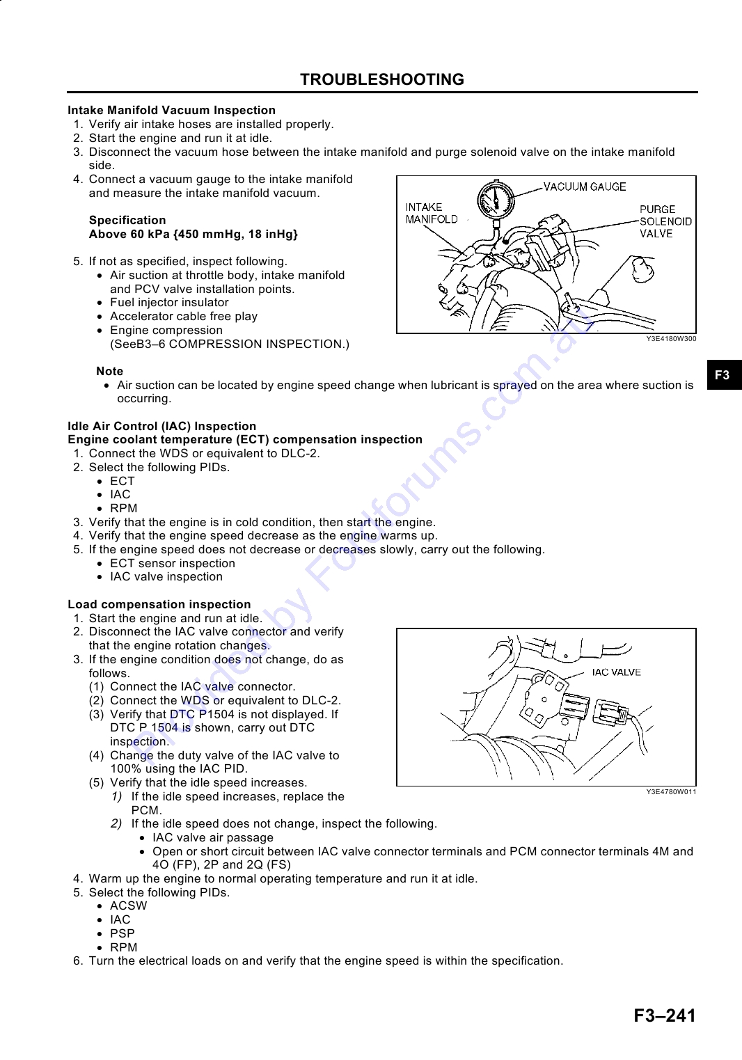
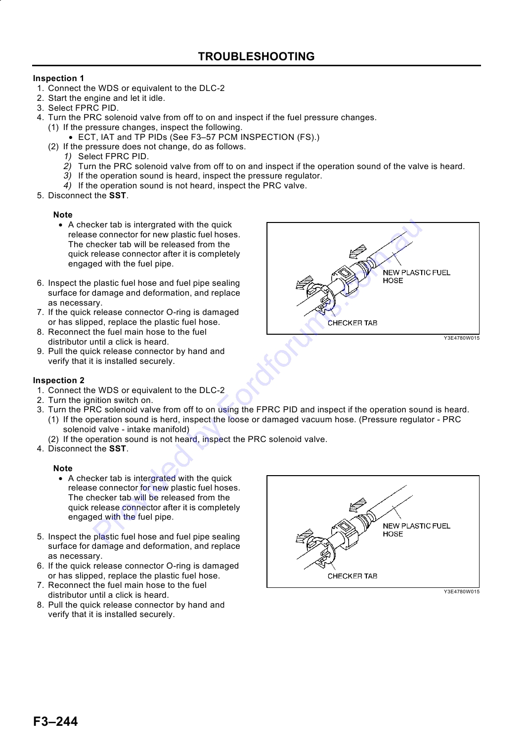
(FP, FS)
PRESSURE REGURATOR
FEATURES
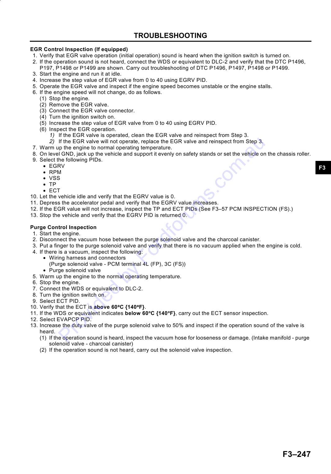
REMOVAL/INSTALLATION .......................... F3-42
PRESSURE REGULATOR INSPECTION ....... F3-42
OUTLINE .............................................................. F3-3
PRC SOLENOID VALVE INSPECTION (FS) .. F3-43
OUTLINE OF CONSTRUCTION ....................... F3-3
FUEL PUMP UNIT INSPECTION .................... F3-44
FEATURES ........................................................ F3-3
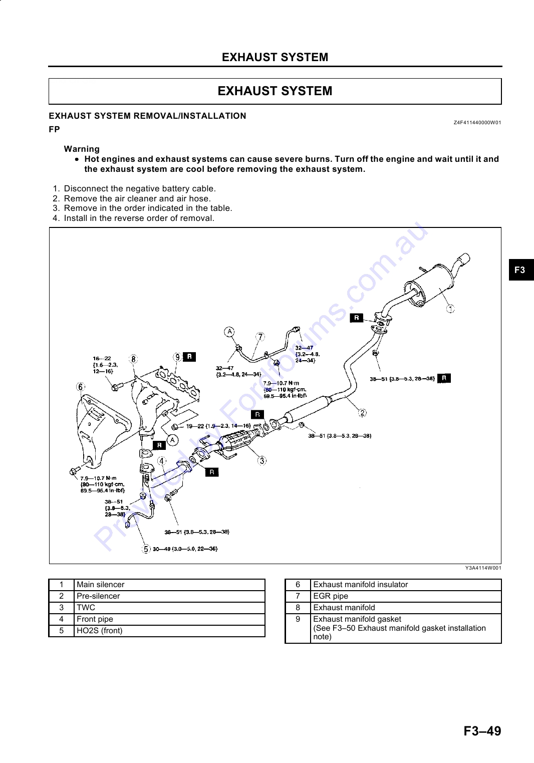
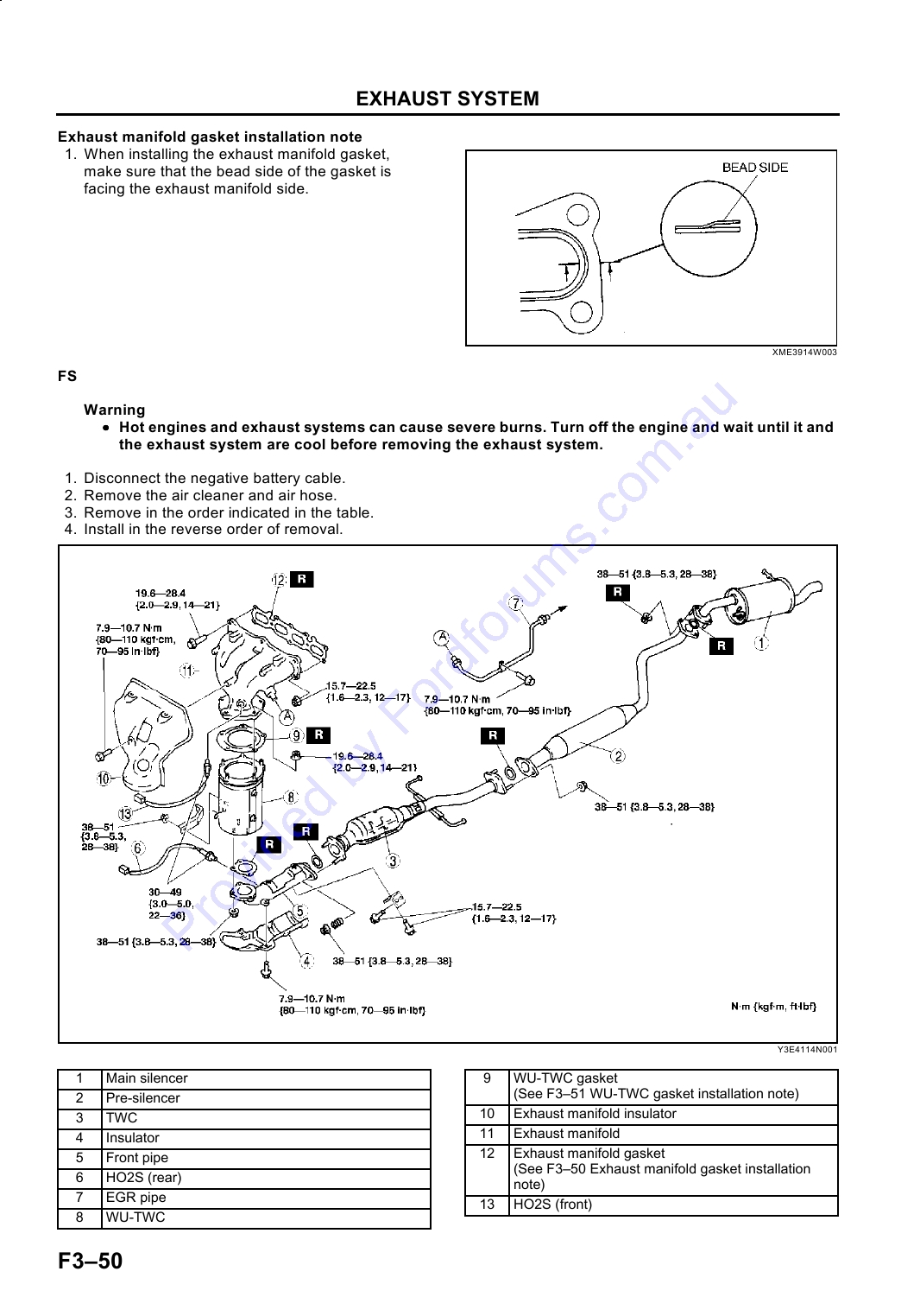
EXHAUST SYSTEM ........................................... F3-49
SPECIFICATIONS ............................................. F3-3
EXHAUST SYSTEM
CONTROL SYSTEM DIAGRAM (FS) ................ F3-4
REMOVAL/INSTALLATION .......................... F3-49
CONTROL SYSTEM WIRING DIAGRAM (FS).. F3-6
EMISSION SYSTEM ........................................... F3-52
FUEL SYSTEM ..................................................... F3-9
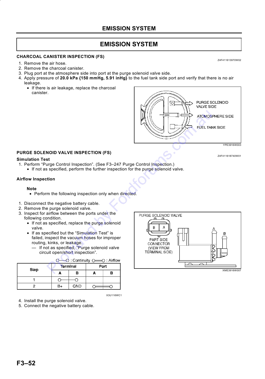
CHARCOAL CANISTER INSPECTION (FS) ... F3-52
OUTLINE ........................................................... F3-9
PURGE SOLENOID VALVE
STRUCTURAL VIEW......................................... F3-9
INSPECTION (FS) ........................................ F3-52
QUICK RELEASE CONNECTOR
F3
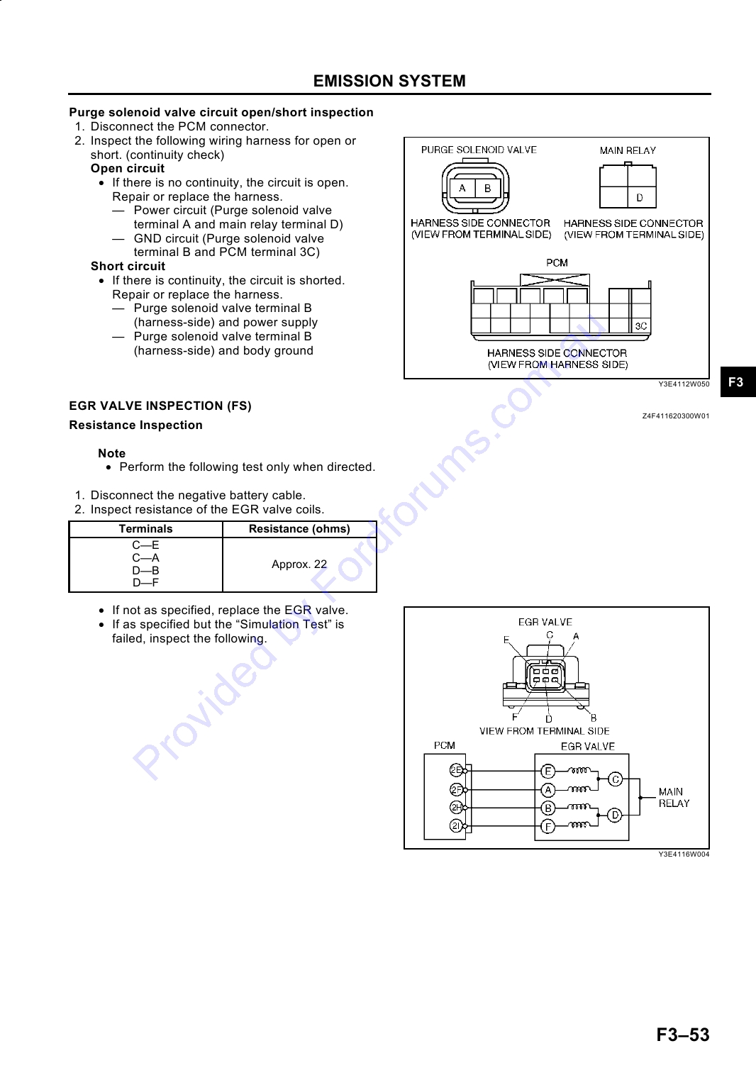
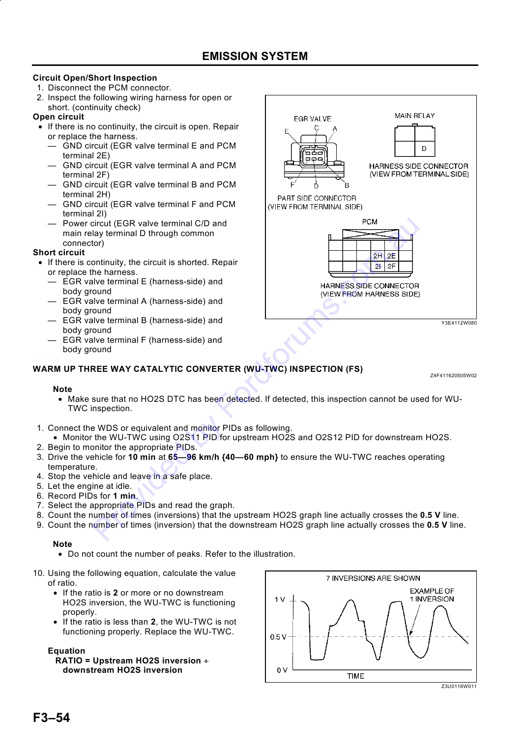
EGR VALVE INSPECTION (FS)...................... F3-53
(ENGINE ROOM SIDE) ................................ F3-10
WARM UP THREE WAY CATALYTIC
QUICK RELEASE CONNECTOR
CONVERTER (WU-TWC) INSPECTION
(FUEL DISTRIBUTOR SIDE)........................ F3-11
(FS) ............................................................... F3-54
EMISSION SYSTEM ........................................... F3-12
CONTROL SYSTEM........................................... F3-56
OUTLINE ......................................................... F3-12
CONTROL SYSTEM COMPONENT
STRUCTURAL VIEW (FS)............................... F3-12
LOCATION INDEX (FS)................................ F3-56
CHARCOAL CANISTER (FS) .......................... F3-13
PCM INSPECTION (FS) .................................. F3-57
WARM UP THREE WAY CATALYTIC
INTAKE AIR TEMPERATURE (IAT) SENSOR
CONVERTER (WU-TWC) (FS)..................... F3-13
INSPECTION (FS) ........................................ F3-71
CONTROL SYSTEM........................................... F3-14
MASS AIR FLOW (MAF) SENSOR
OUTLINE ......................................................... F3-14
INSPECTION (FS) ........................................ F3-72
BLOCK DIAGRAM (FS) ................................... F3-14
THROTTLE POSITION (TP) SENSOR
CONTROL DEVICES AND CONTROL
INSPECTION (FS) ........................................ F3-72
RELATIONSHIP CHART (FS) ...................... F3-16
THROTTLE POSITION (TP) SENSOR
BAROMETRIC PRESSURE SENSOR (FS) .... F3-18
ADJUSTMENT (FS) ...................................... F3-73
REAR HEATED OXYGEN SENSOR
ENGINE COOLANT TEMPERATURE (ECT)
(HO2S) (FS).................................................. F3-19
SENSOR INSPECTION (FS) ........................ F3-74
ON-BOARD DIAGNOSTIC ................................. F3-21
CAMSHAFT POSITION (CMP) SENSOR
OUTLINE ......................................................... F3-21
INSPECTION (FS) ........................................ F3-75
DIAGNOSTIC TEST MODE (FS)..................... F3-21
CRANKSHAFT POSITION (CKP) SENSOR
DTC (FS).......................................................... F3-24
INSPECTION (FS) ........................................ F3-76
PID/DATA MONITOR AND RECORD ............. F3-27
KNOCK SENSOR INSPECTION (FS) ............. F3-77
SIMULATION TEST......................................... F3-28
BAROMETRIC PRESSURE SENSOR
INSPECTION (FS) ........................................ F3-77
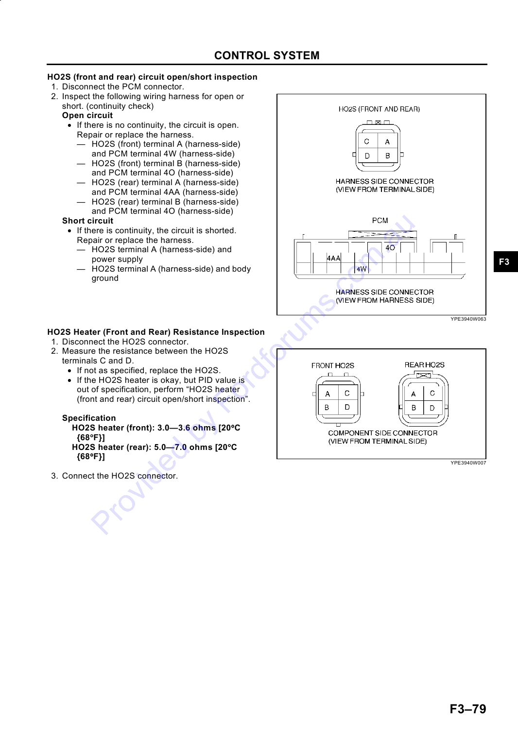
HEATED OXYGEN SENSOR (HO2S)
SERVICE
(FRONT AND REAR) INSPECTION (FS)..... F3-78
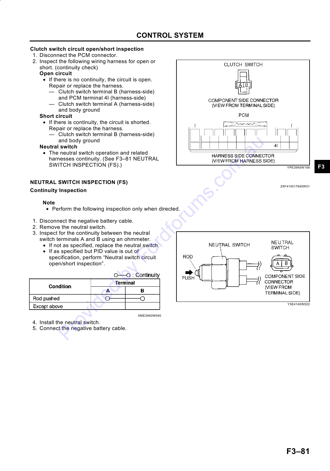
CLUTCH SWITCH INSPECTION (FS) ............ F3-80
OUTLINE ............................................................ F3-29
NEUTRAL SWITCH INSPECTION (FS) .......... F3-81
SUPPLEMENTAL SERVICE INFORMATION . F3-29
POWER STEERING PRESSURE (PSP)
ENGINE TUNE-UP ............................................. F3-30
SWITCH INSPECTION (FS) ......................... F3-82
ENGINE TUNE-UP PREPARATION ............... F3-30
ON-BOARD DIAGNOSTIC ................................. F3-83
IGNITION TIMING INSPECTION .................... F3-30
FOREWORD .................................................... F3-83
IDLE SPEED ADJUSTMENT........................... F3-31
OBD PENDING TROUBLE CODES (FS) ........ F3-83
IDLE-UP SPEED INSPECTION....................... F3-31
OBD FREEZE FRAME DATA (FS) .................. F3-83
INTAKE-AIR SYSTEM........................................ F3-32
OBD ON-BOARD SYSTEM READINESS
VACUUM HOSE ROUTING DIAGRAM (FS) ... F3-32
TEST (FS) ..................................................... F3-83
IDLE AIR CONTROL (IAC) VALVE
OBD DIAGNOSTIC MONITORING TEST
INSPECTION (FS) ........................................ F3-32
RESULTS (FS).............................................. F3-84
VARIABLE INERTIA CHARGING SYSTEM
OBD READ/CLEAR DIAGNOSTIC TEST
(VICS) SOLENOID VALVE INSPECTION
RESULTS (FS).............................................. F3-84
(FS) ............................................................... F3-33
OBD PARAMETER IDENTIFICATION (PID)
FUEL SYSTEM ................................................... F3-35
ACCESS (FS) ............................................... F3-84
FUEL PRESSURE INSPECTION .................... F3-35
ON-BOARD DIAGNOSTIC TEST (FS) ............ F3-84
FUEL INJECTOR REMOVAL/INSTALLATION F3-37
OBD DRIVE MODE (FS).................................. F3-86
FUEL INJECTOR INSPECTION (FS) .............. F3-40
F31
TROUBLESHOOTING ...................................... F3-198
DIAGNOSTIC MONITORING TEST
FOREWORD .................................................. F3-198
RESULTS (FS).............................................. F3-88
TROUBLESHOOTING ITEM TABLE ............. F3-198
DTC TABLE (FS) ............................................. F3-88
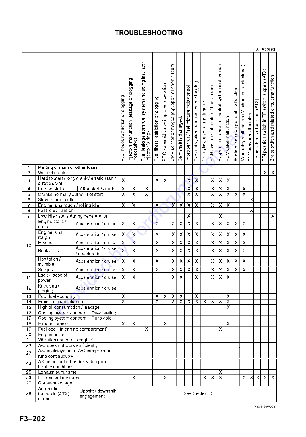
QUICK DIAGNOSIS CHART.......................... F3-200
DTC P0031 (FS) .............................................. F3-92
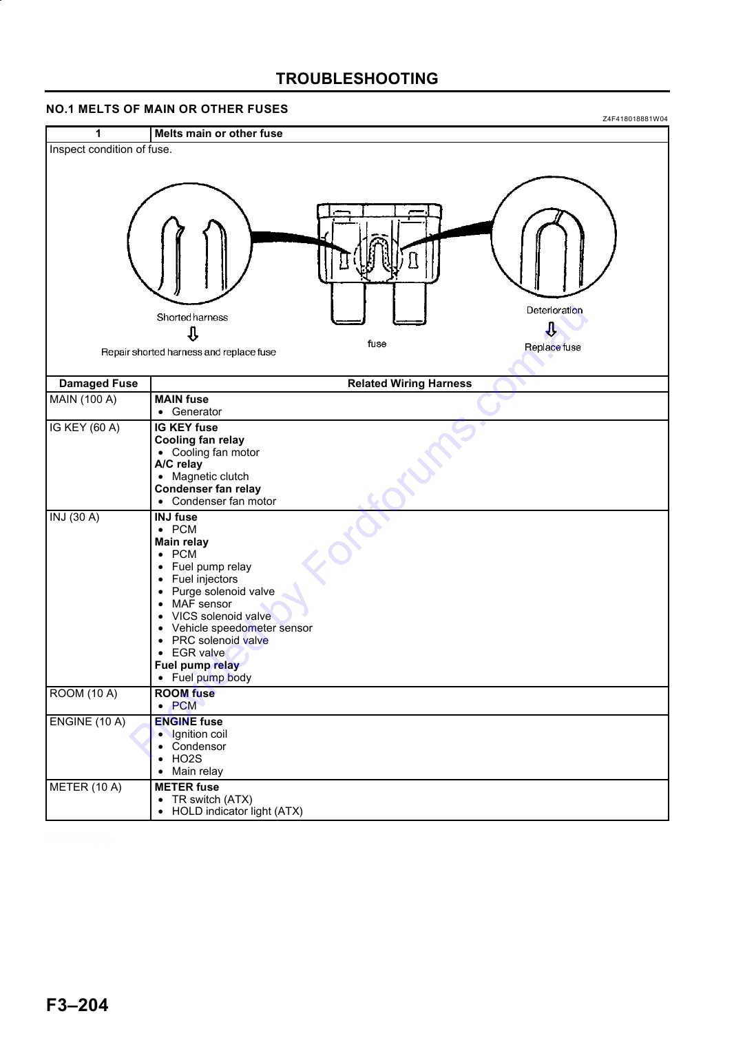
NO.1 MELTS OF MAIN OR OTHER FUSES . F3-204
DTC P0032 (FS) .............................................. F3-93
NO.2 WILL NOT CRANK ............................... F3-205
DTC P0037 (FS) .............................................. F3-95
NO.3 HARD START/LONG CRANK/ERRATIC
DTC P0038 (FS) .............................................. F3-97
START/ERRATIC CRANK .......................... F3-206
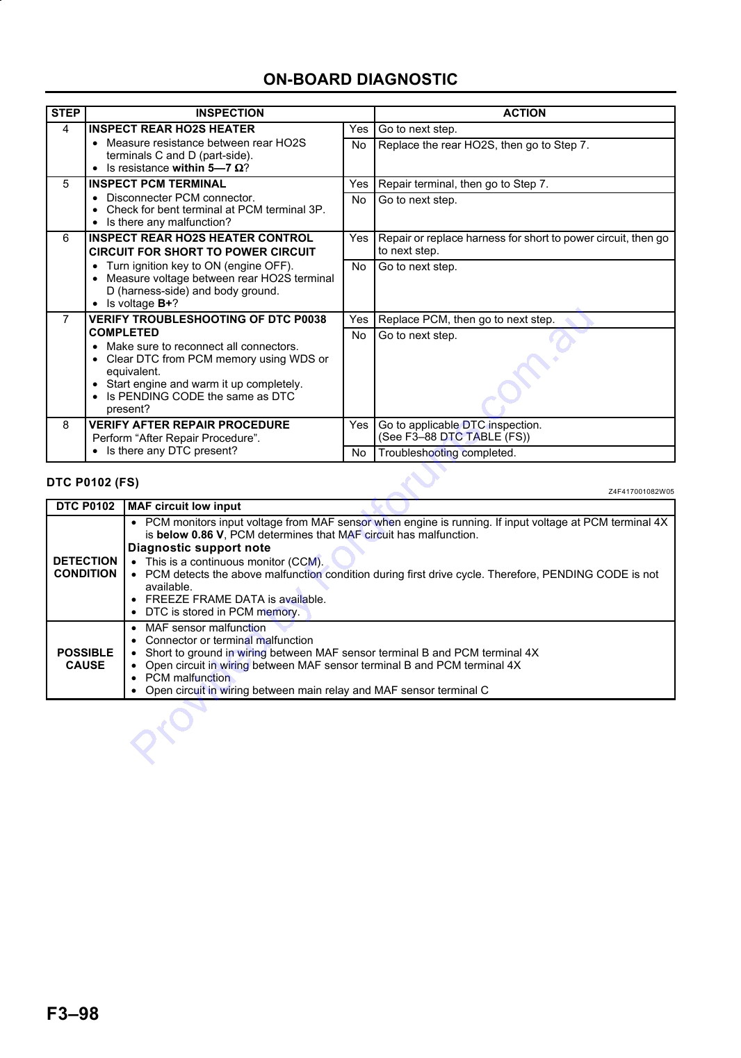
DTC P0102 (FS) .............................................. F3-98
NO.4 ENGINE STALLS-AFTER START/AT
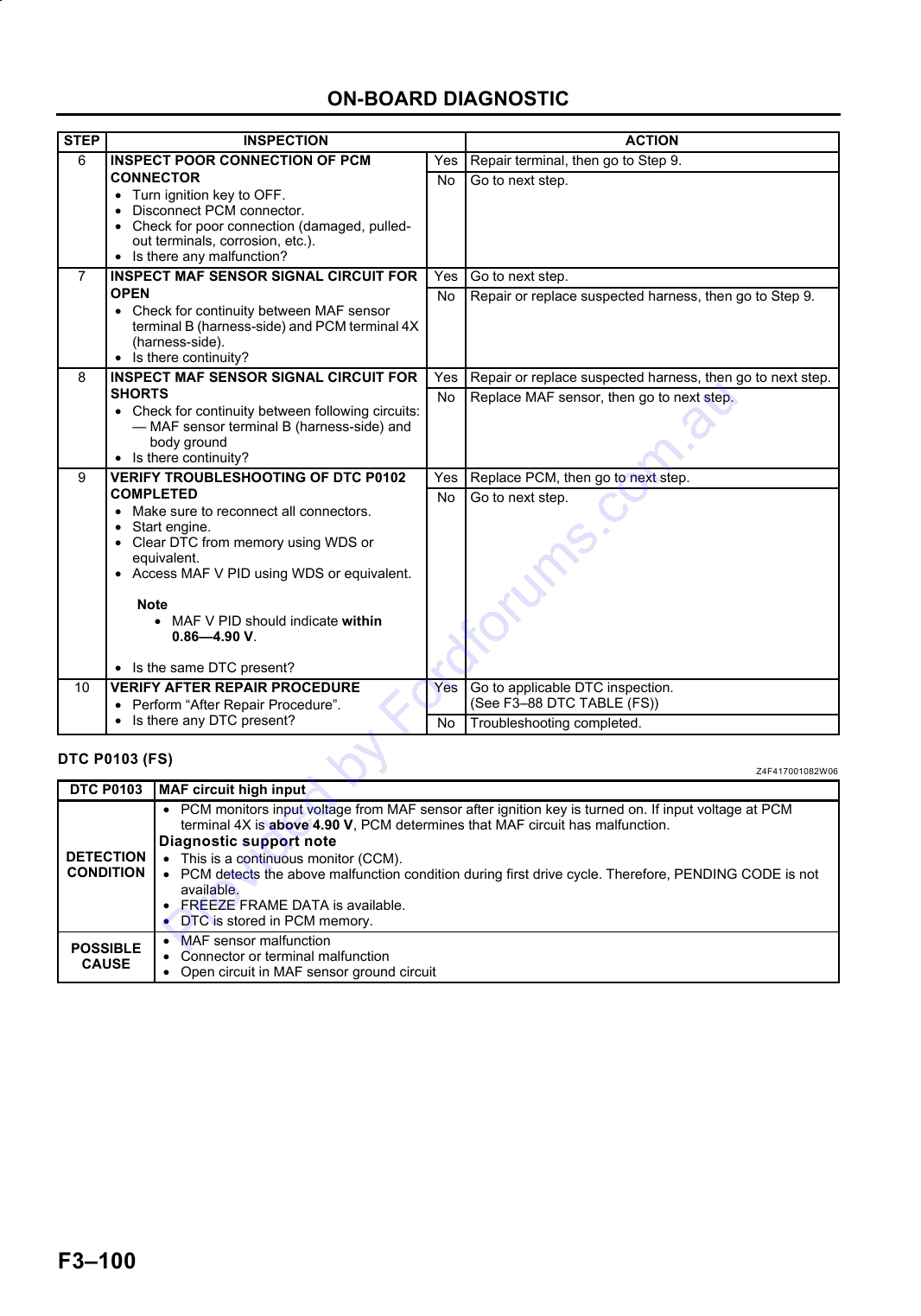
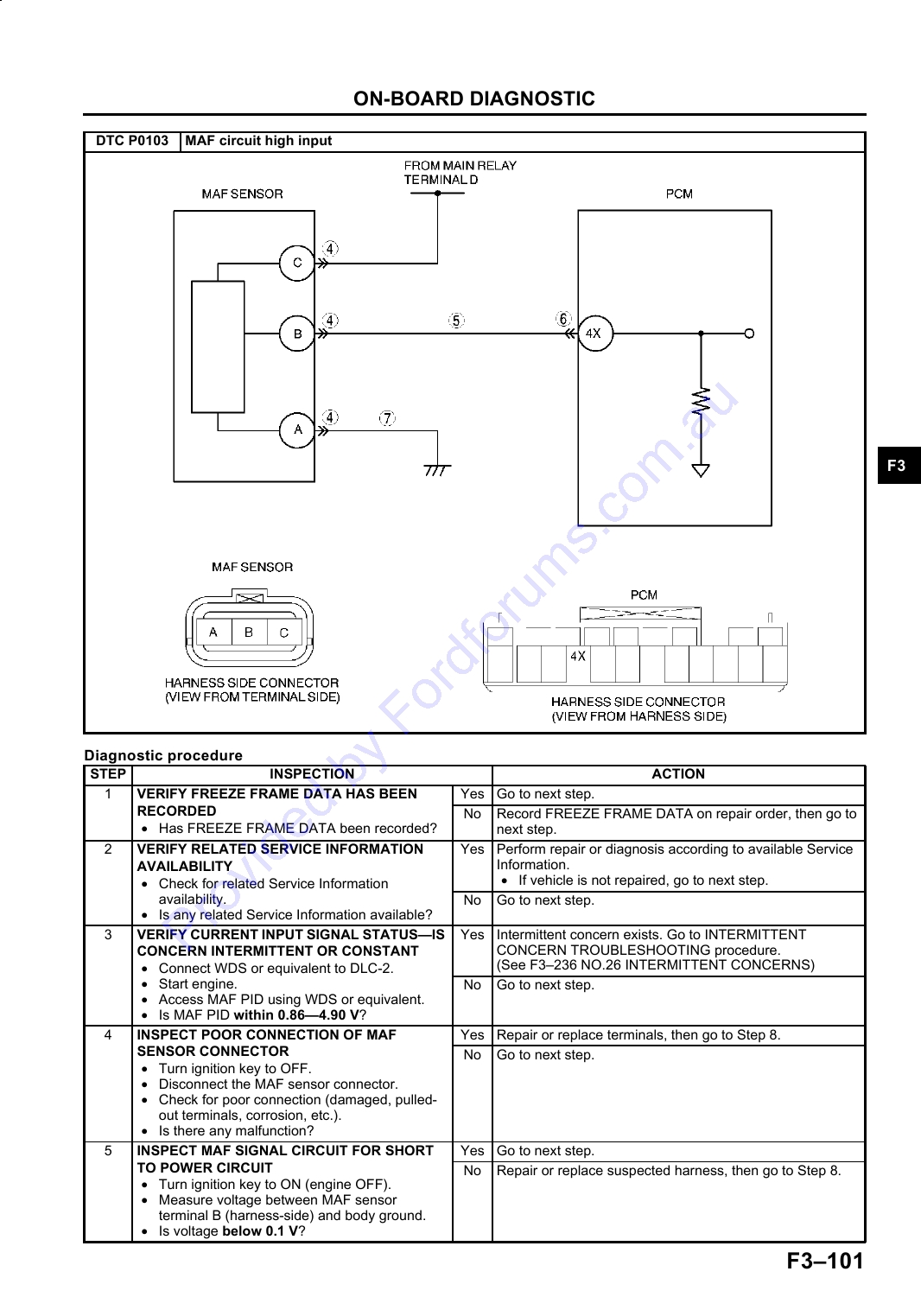
DTC P0103 (FS) ............................................ F3-100
IDLE ............................................................ F3-208
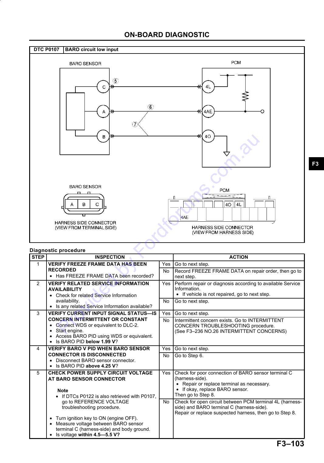
DTC P0107 (FS) ............................................ F3-102
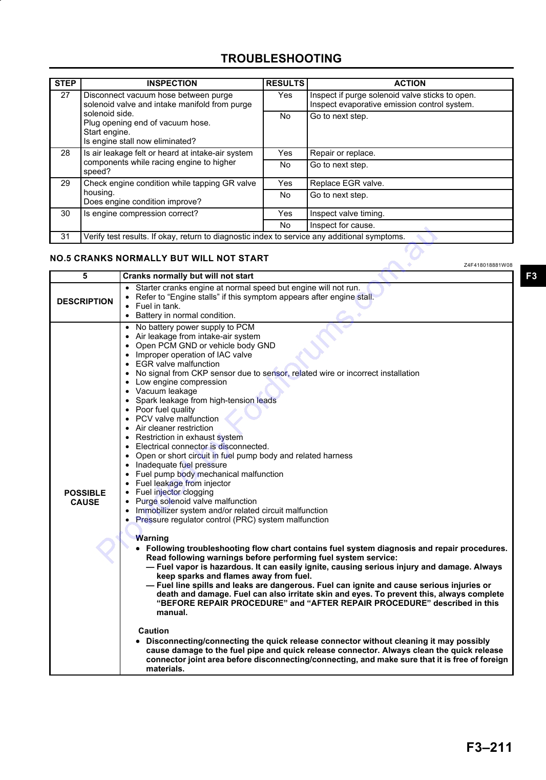
NO.5 CRANKS NORMALLY BUT WILL
DTC P0108 (FS) ............................................ F3-104
NOT START................................................ F3-211
DTC P0111 (FS) ............................................ F3-106
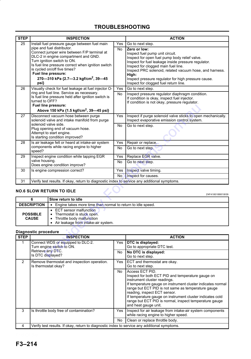
NO.6 SLOW RETURN TO IDLE .................... F3-214
DTC P0112 (FS) ............................................ F3-107
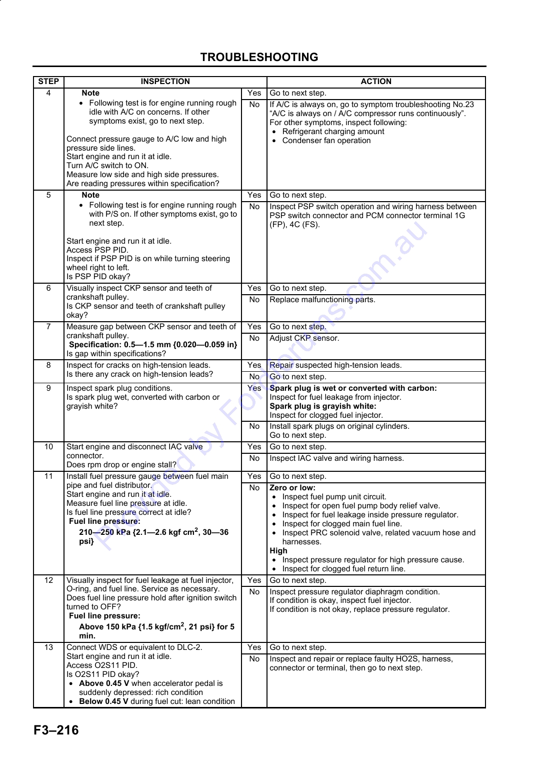
NO.7 ENGINE RUNS ROUGH/ROLLING
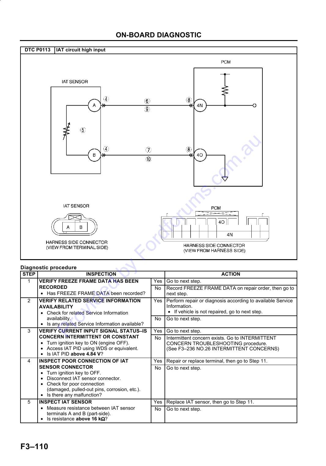
DTC P0113 (FS) ............................................ F3-109
IDLE ............................................................ F3-215
DTC P0117 (FS) ............................................ F3-111
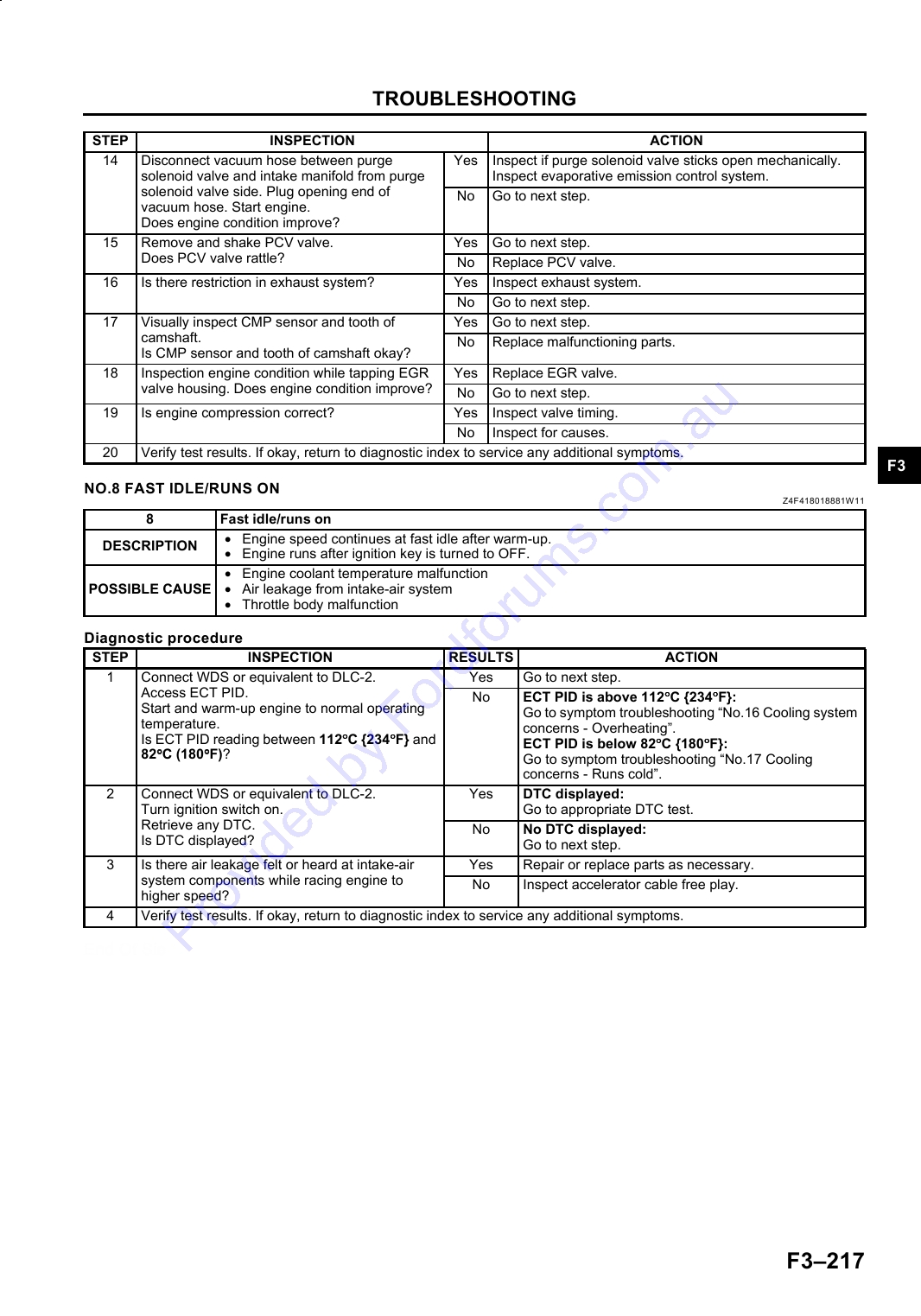
NO.8 FAST IDLE/RUNS ON .......................... F3-217
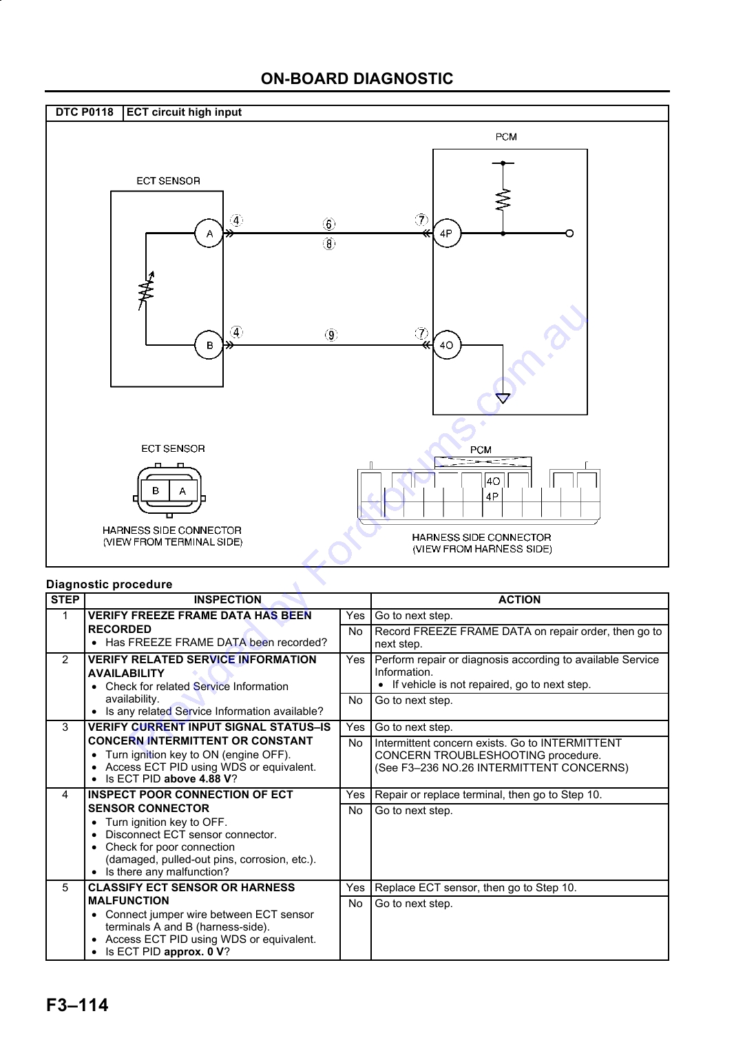
DTC P0118 (FS) ............................................ F3-113
NO.9 LOW IDLE/STALLS DURING
DTC P0122 (FS) ............................................ F3-115
DECELERATION ........................................ F3-218
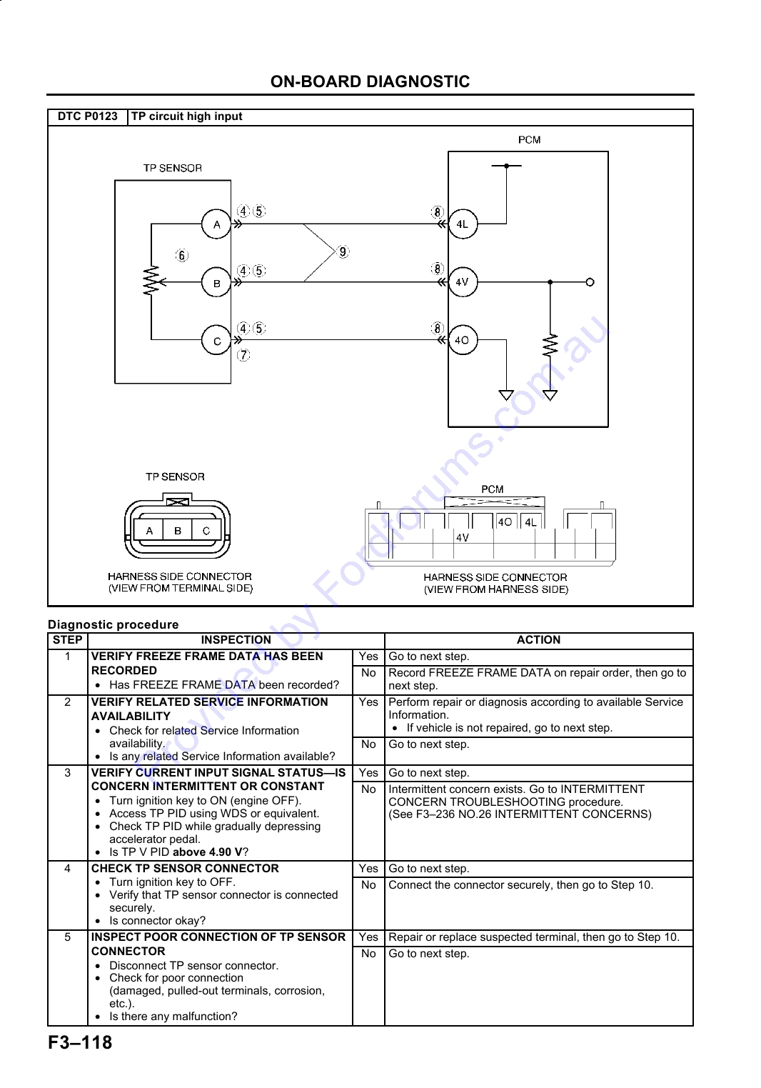
DTC P0123 (FS) ............................................ F3-117
NO.10 ENGINE STALLS/QUITS, ENGINE
DTC P0125 (FS) ............................................ F3-119
RUNS ROUGH, MISSES, BUCK/JERK,
DTC P0130 (FS) ............................................ F3-120
HESITATION/STUMBLE, SURGES ........... F3-219
DTC P0134 (FS) ............................................ F3-123
NO.11 LACK/LOSS OF
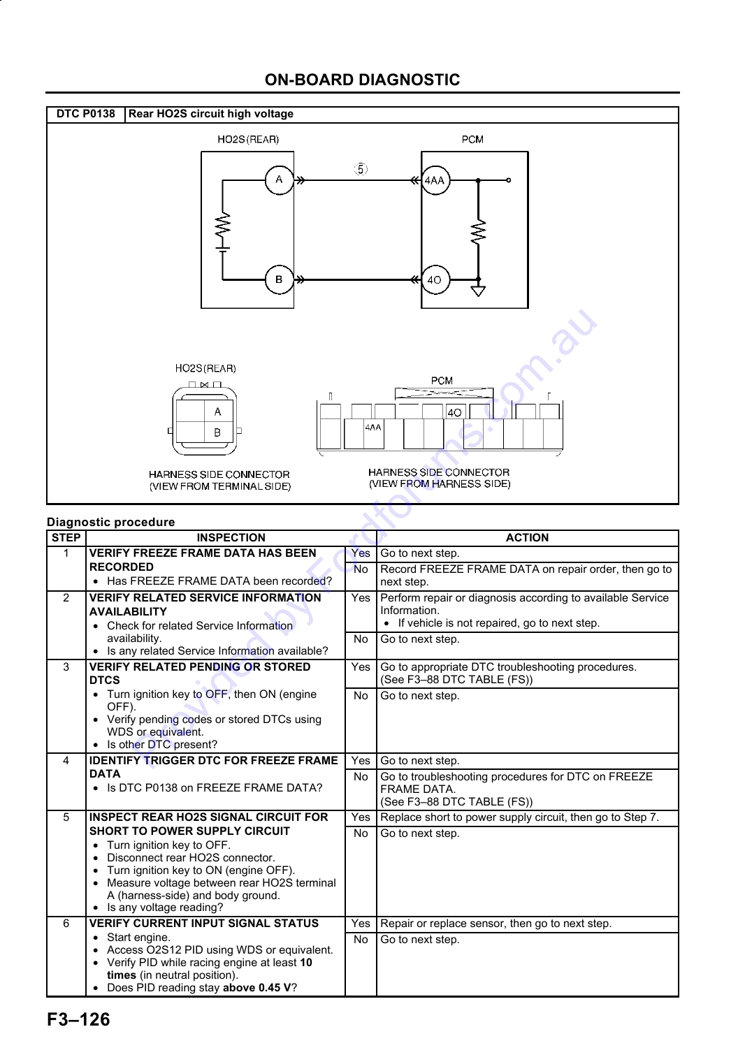
DTC P0138 (FS) ............................................ F3-125
POWER-ACCELERATION/CRUISE ........... F3-222
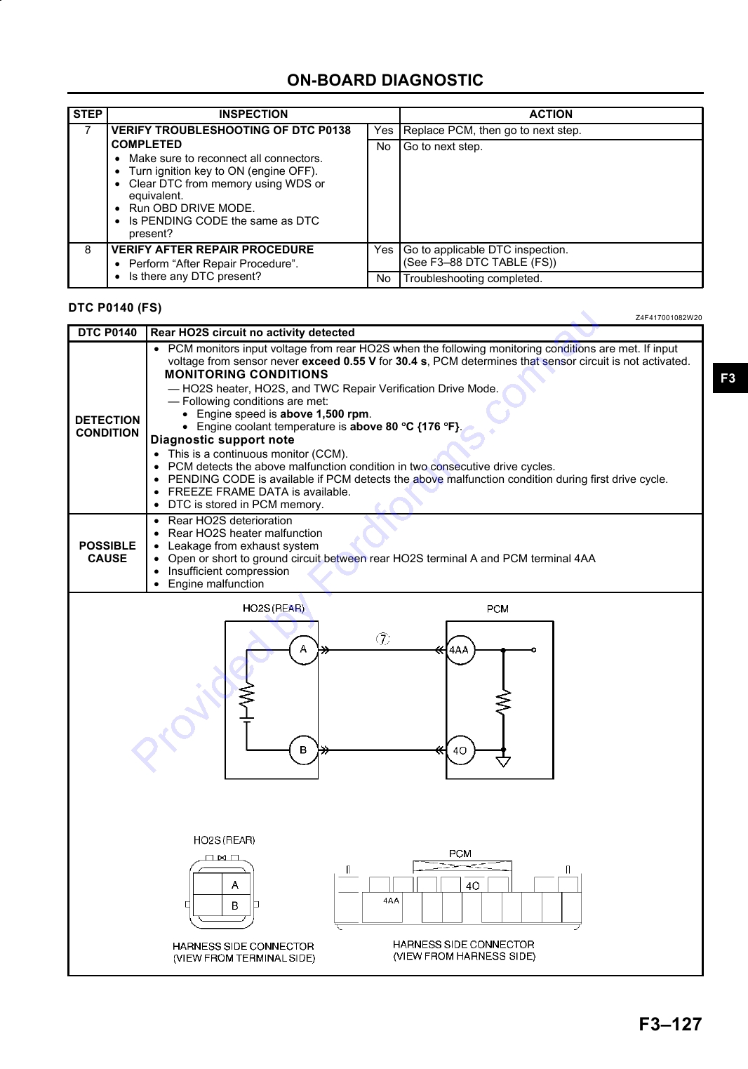
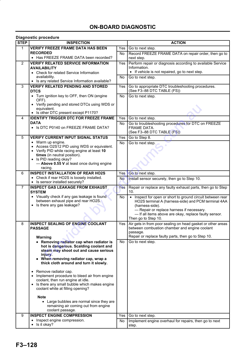
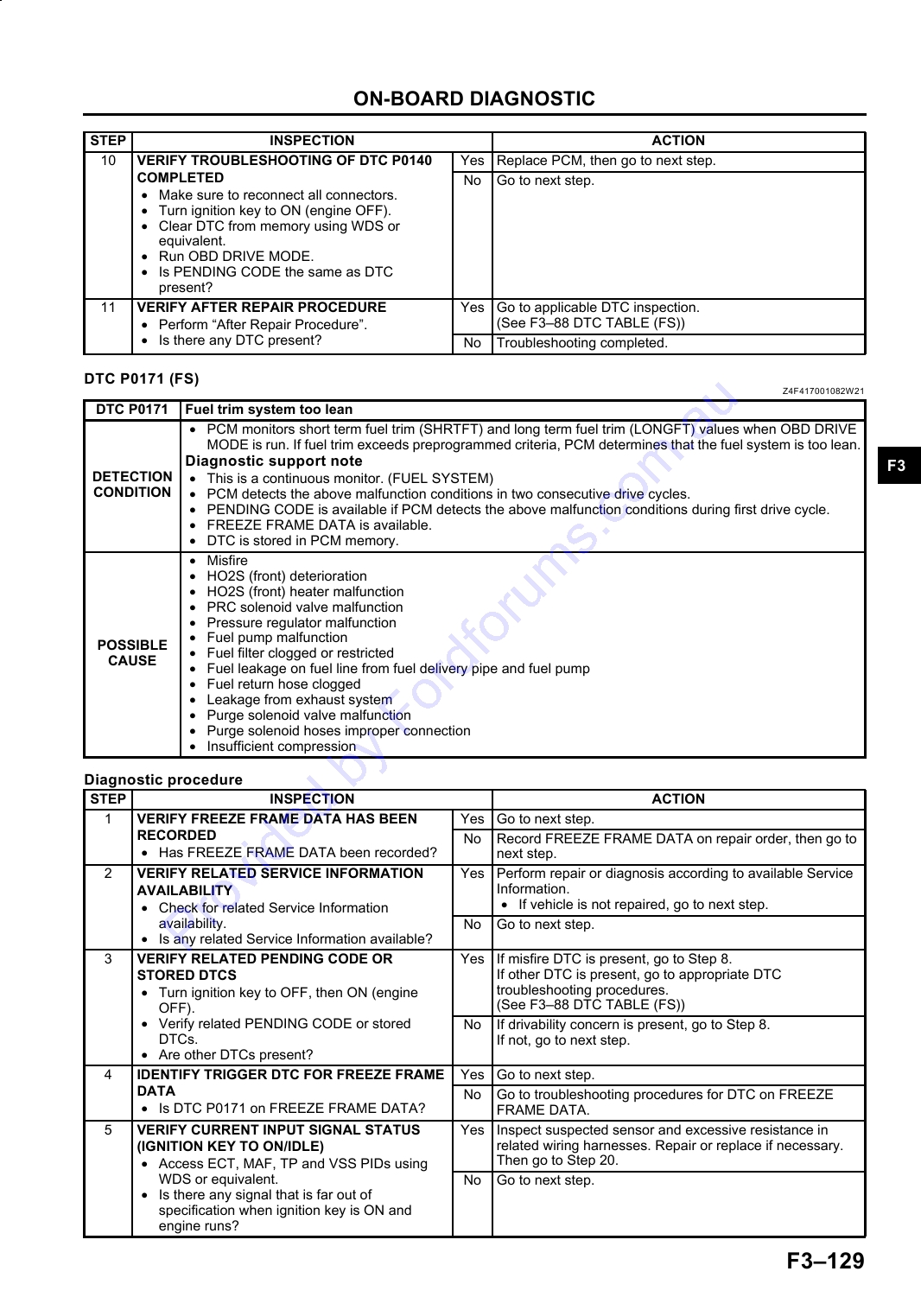
DTC P0140 (FS) ............................................ F3-127
NO.12 KNOCKING/PINGING-
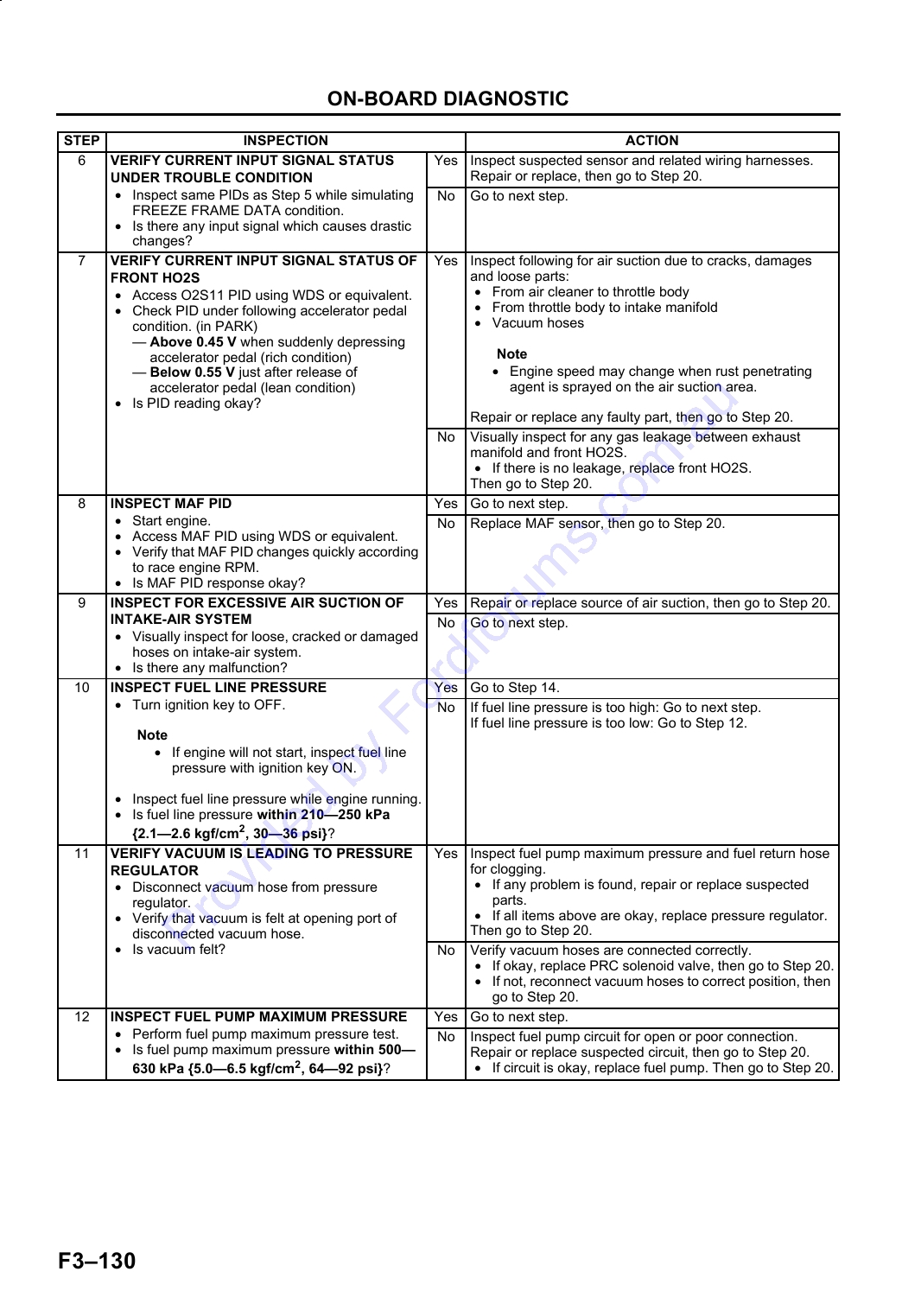
DTC P0171 (FS) ............................................ F3-129
ACCELERATION/CRUISE.......................... F3-224
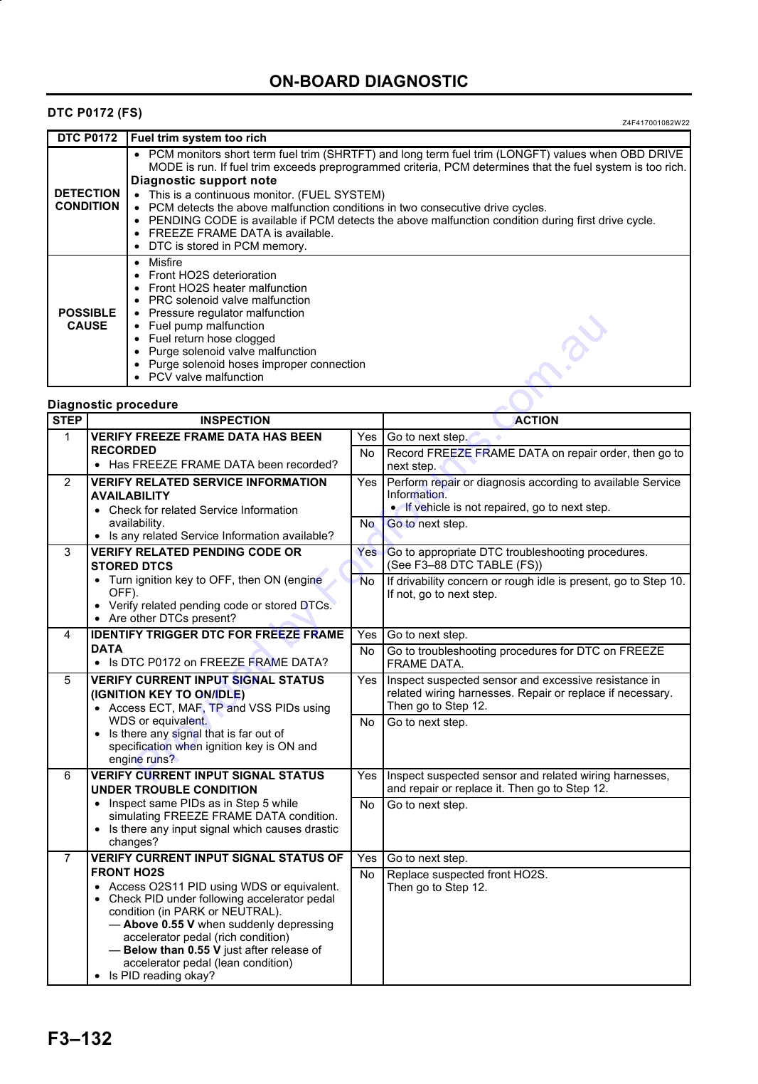
DTC P0172 (FS) ............................................ F3-132
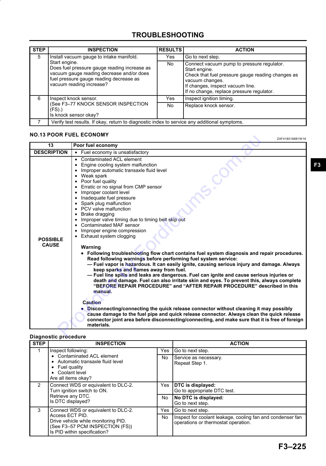
NO.13 POOR FUEL ECONOMY.................... F3-225
DTC P0300 (FS) ............................................ F3-133
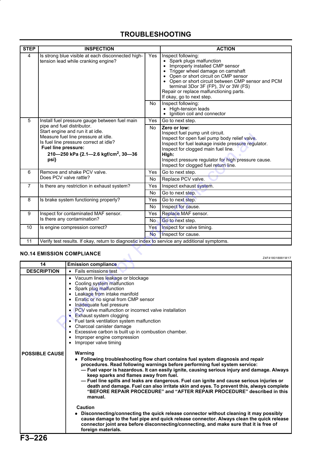
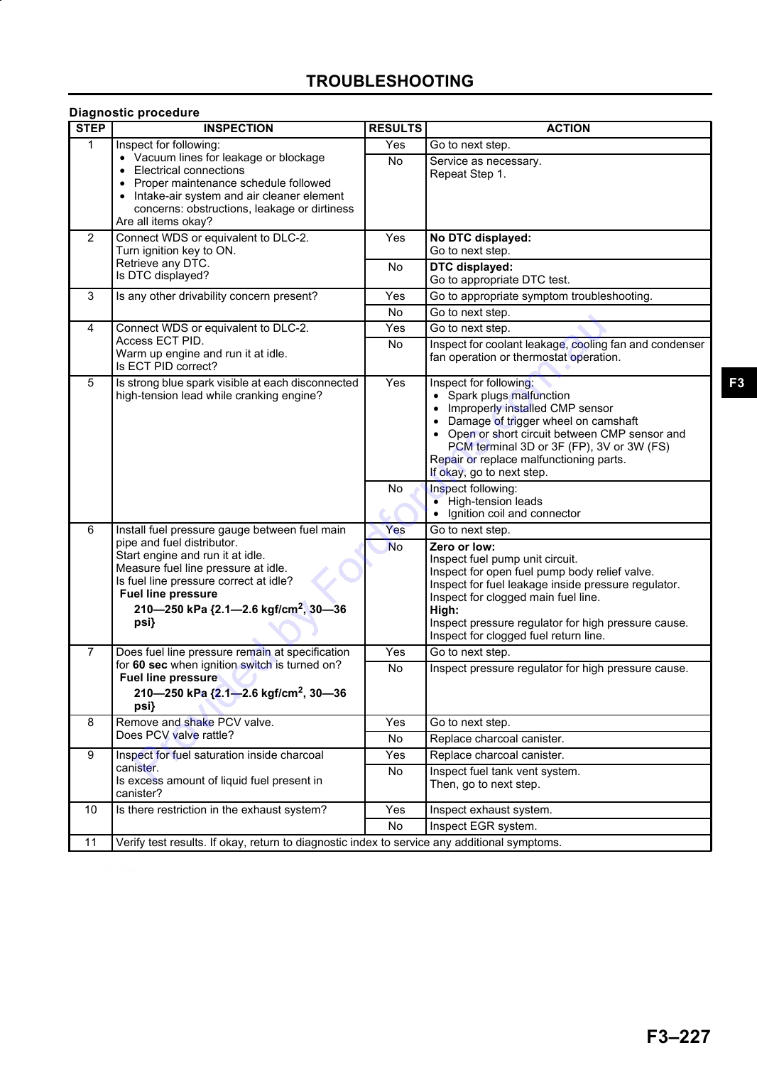
NO.14 EMISSION COMPLIANCE.................. F3-226
DTC P0301, P0302, P0303, P0304 (FS) ....... F3-137
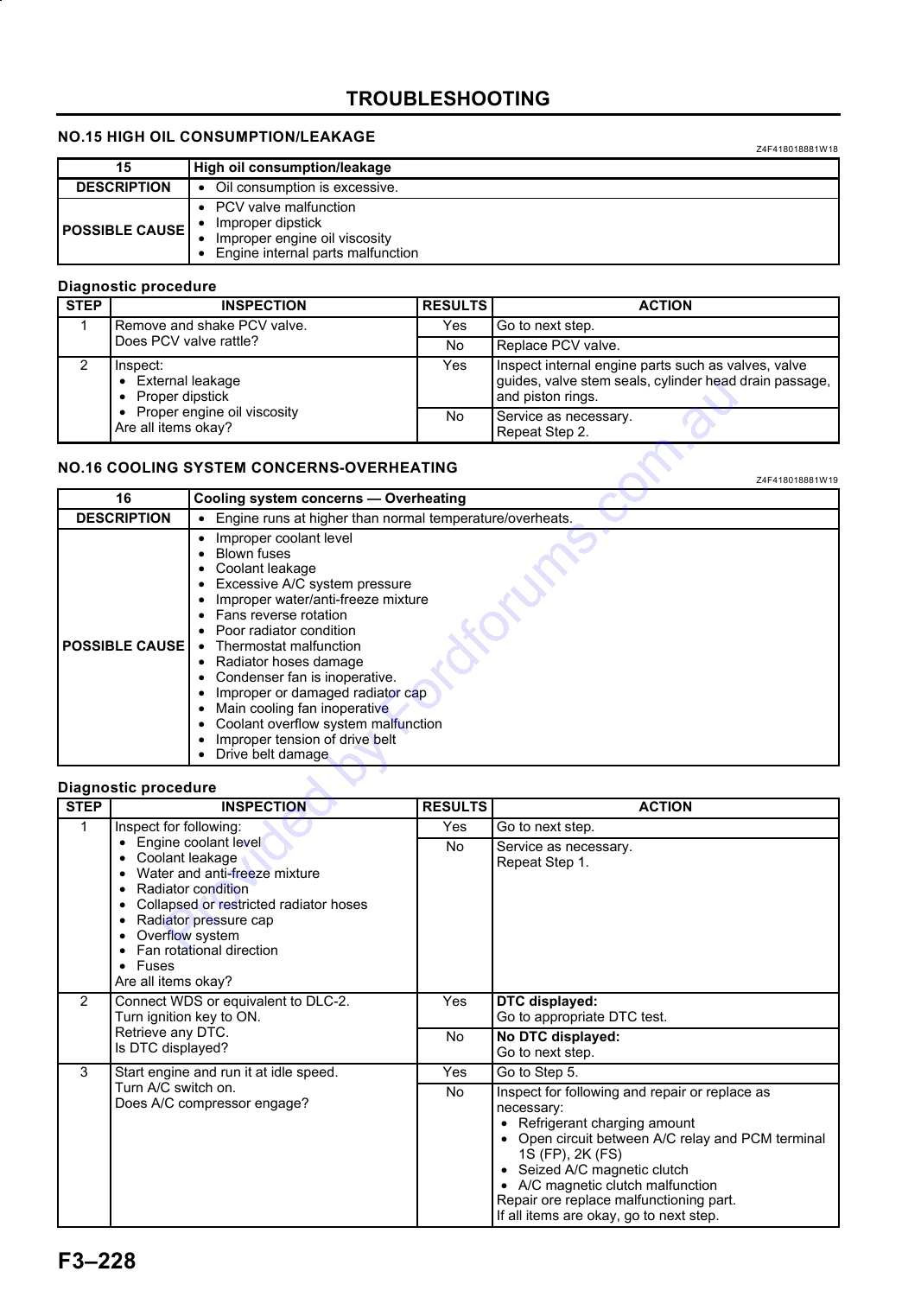
NO.15 HIGH OIL
DTC P0327 (FS) ............................................ F3-139
CONSUMPTION/LEAKAGE ....................... F3-228
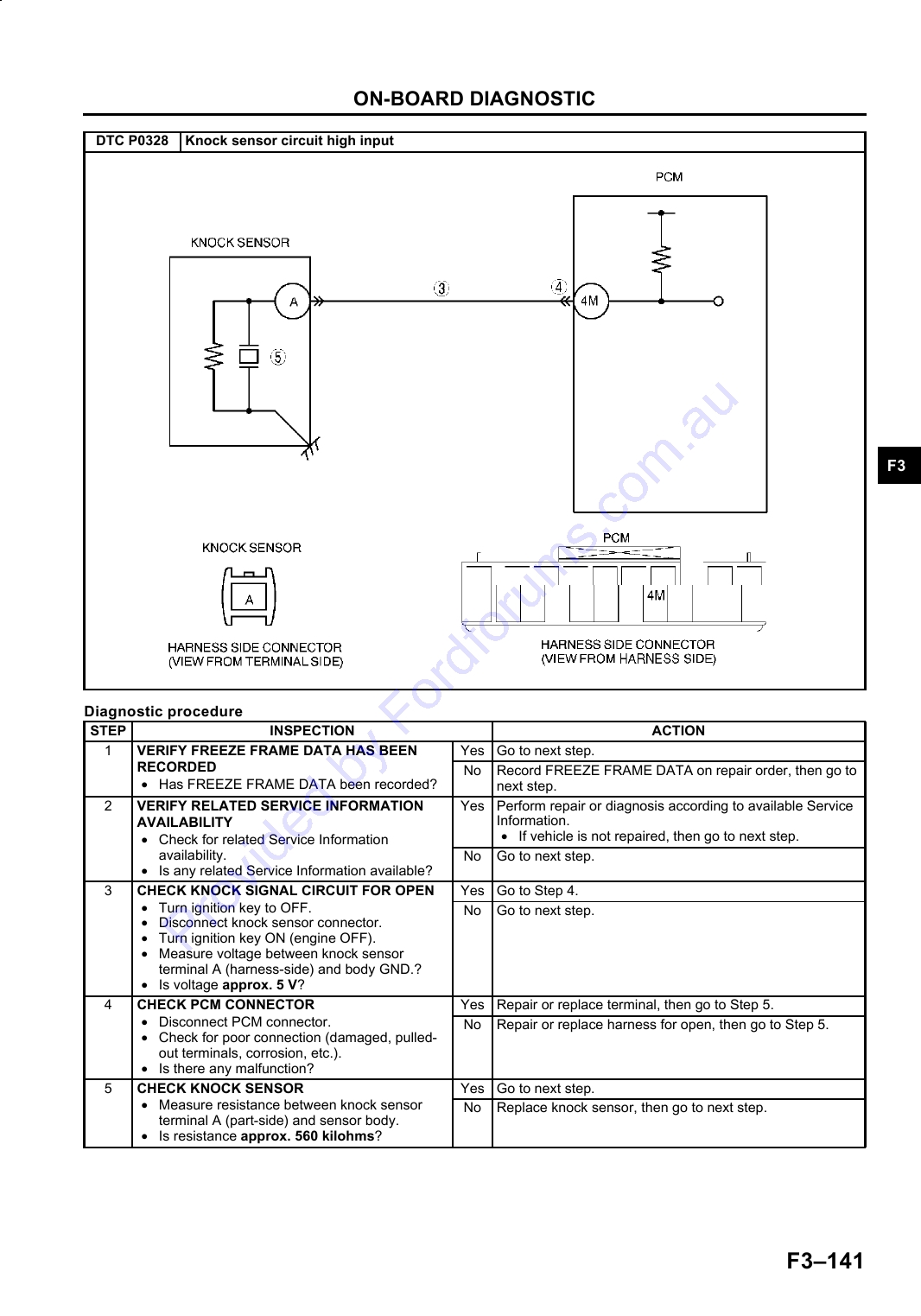
DTC P0328 (FS) ............................................ F3-140
NO.16 COOLING SYSTEM
DTC P0335 (FS) ............................................ F3-142
CONCERNS-OVERHEATING .................... F3-228
DTC P0421 (FS) ............................................ F3-144
NO.17 COOLING SYSTEM
DTC P0443 (FS) ............................................ F3-145
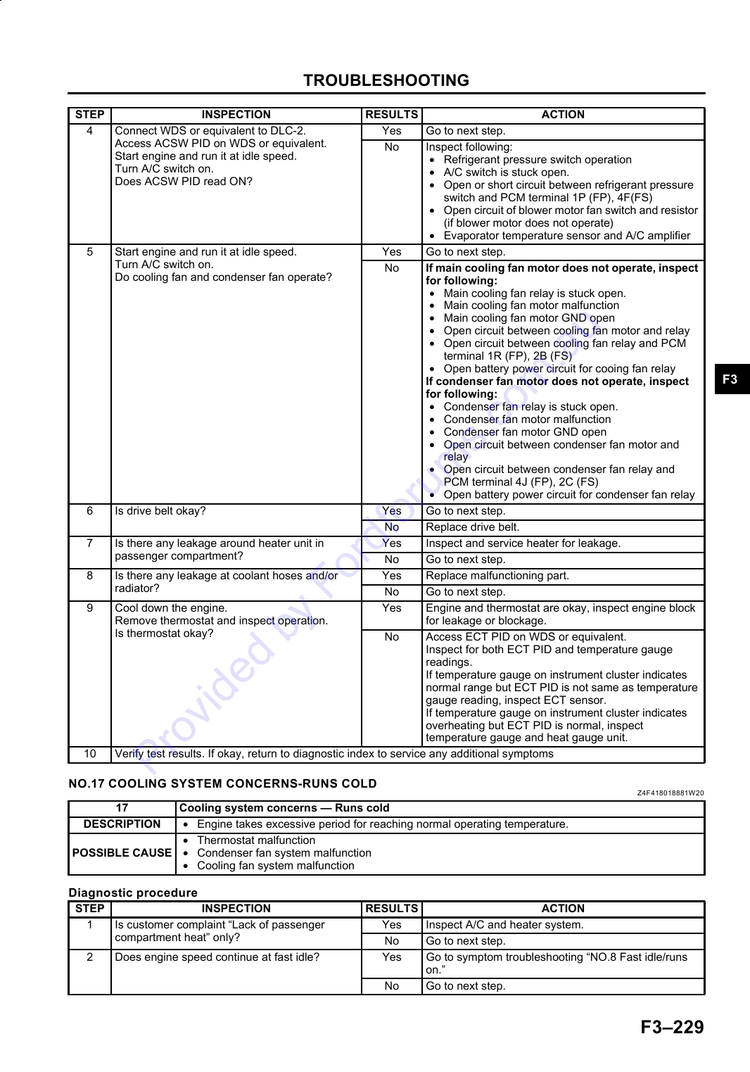
CONCERNS-RUNS COLD ......................... F3-229
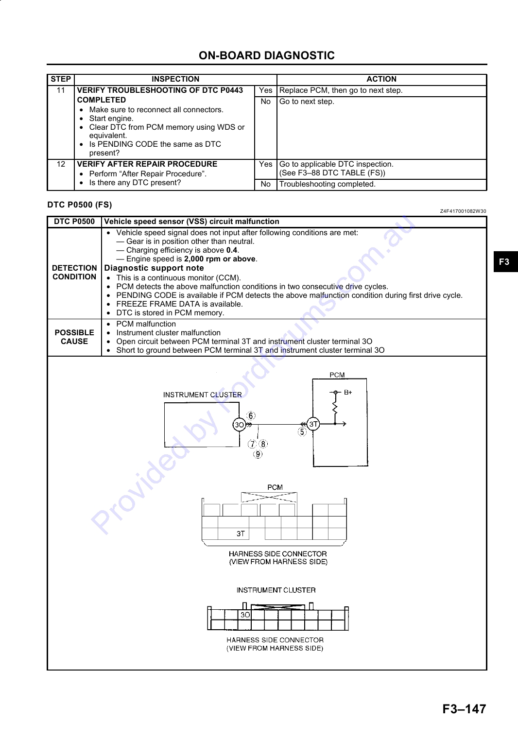
DTC P0500 (FS) ............................................ F3-147
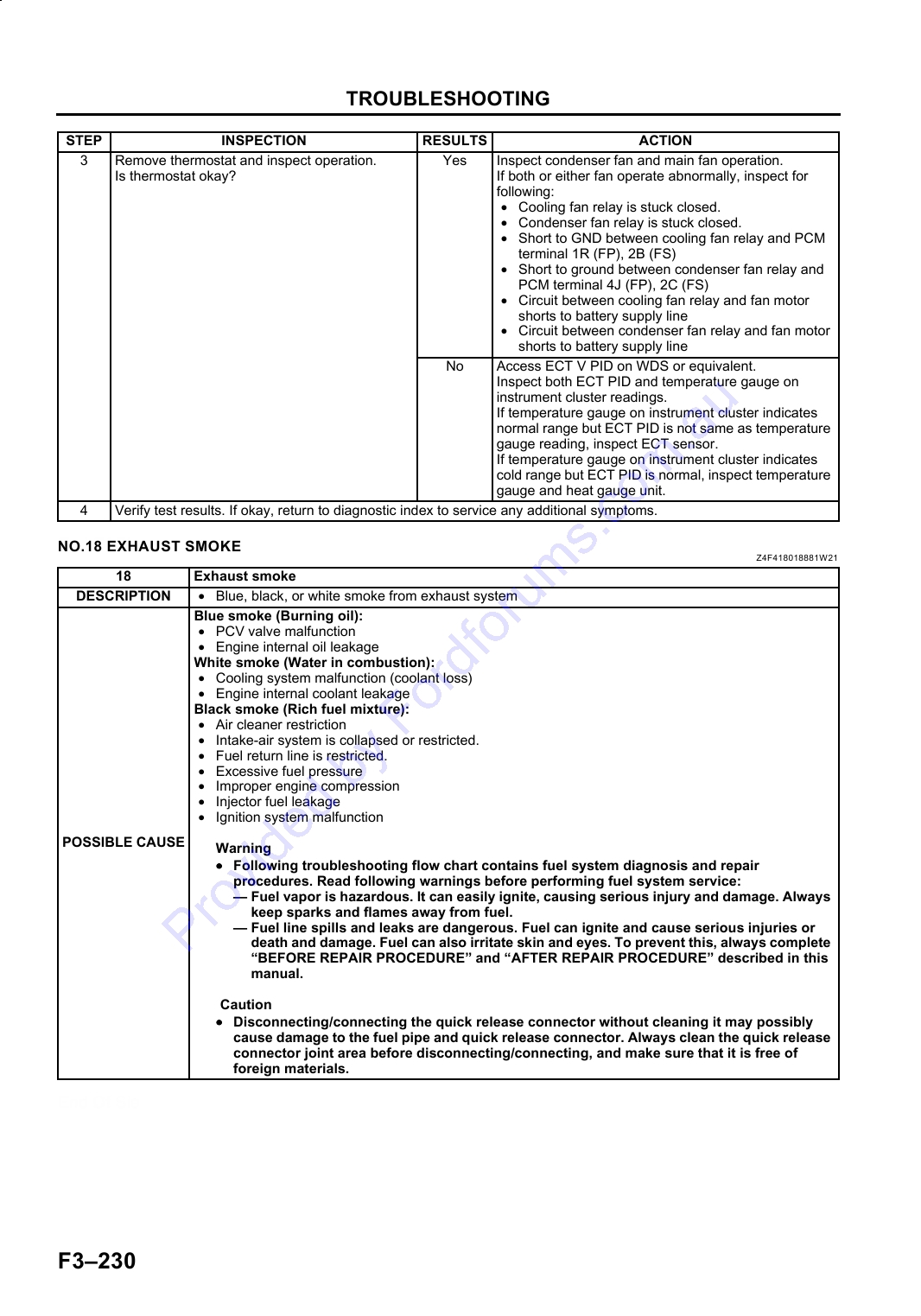
NO.18 EXHAUST SMOKE ............................. F3-230
DTC P0506 (FS) ............................................ F3-149
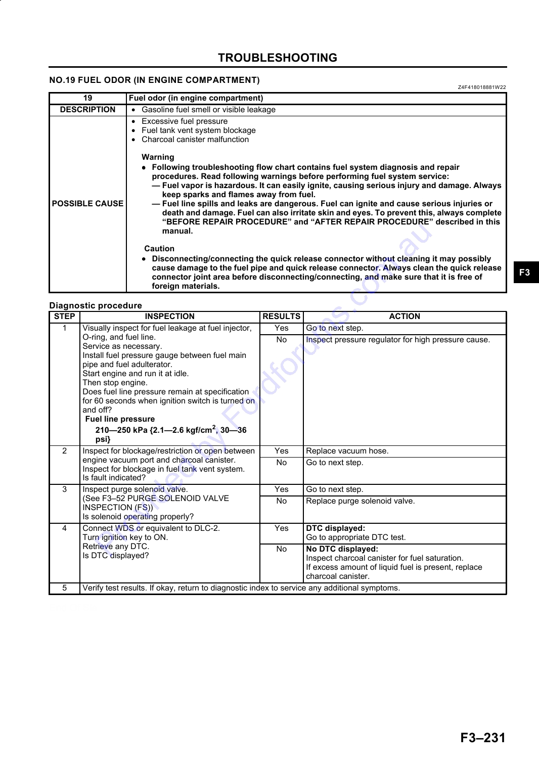
NO.19 FUEL ODOR (IN ENGINE
DTC P0507 (FS) ............................................ F3-150
COMPARTMENT) ....................................... F3-231
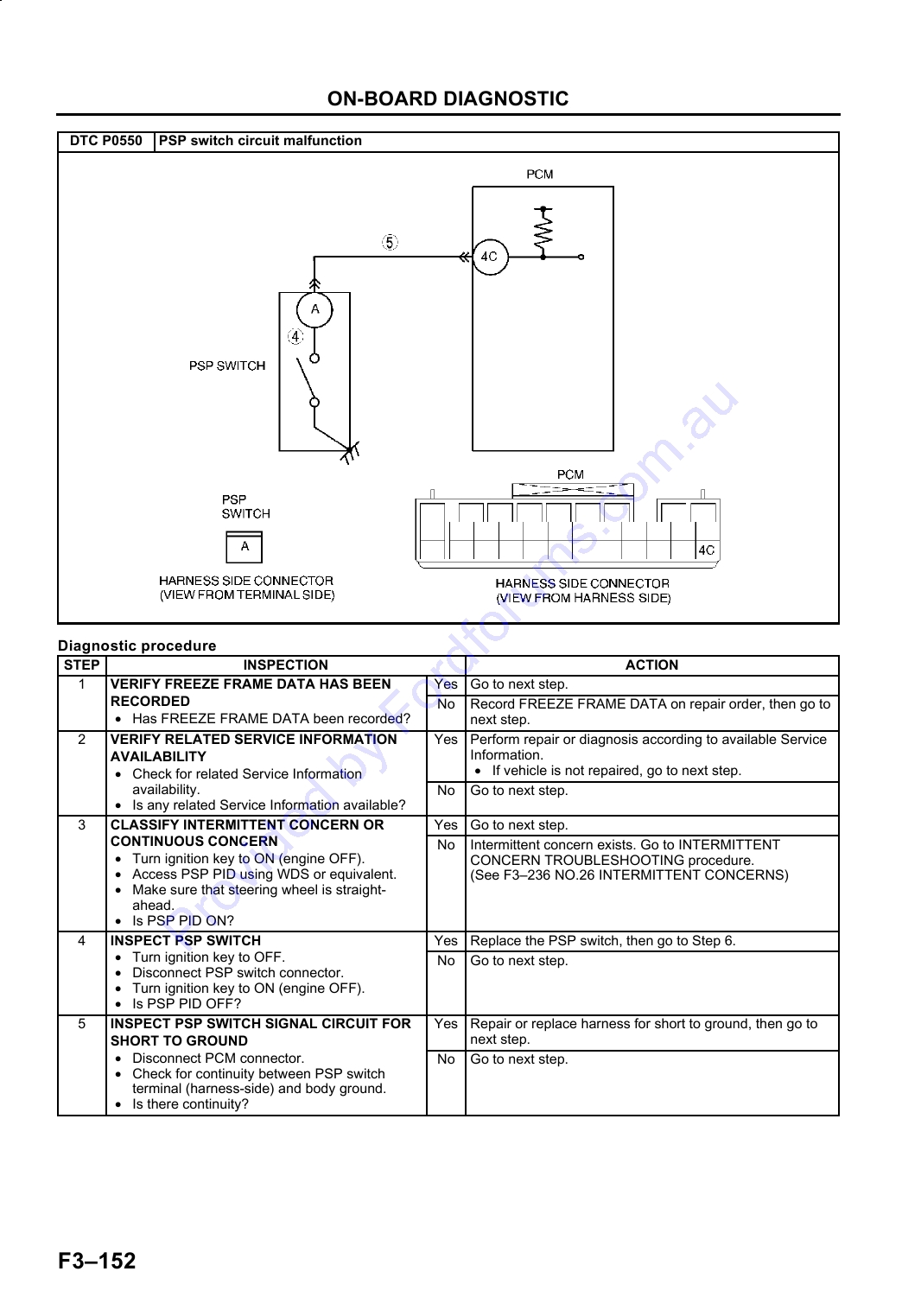
DTC P0550 (FS) ............................................ F3-151
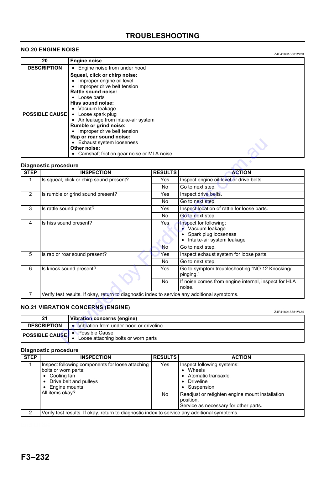
NO.20 ENGINE NOISE .................................. F3-232
DTC P0605 (FS) ............................................ F3-153
NO.21 VIBRATION CONCERNS (ENGINE).. F3-232
DTC P0703 (FS) ............................................ F3-153
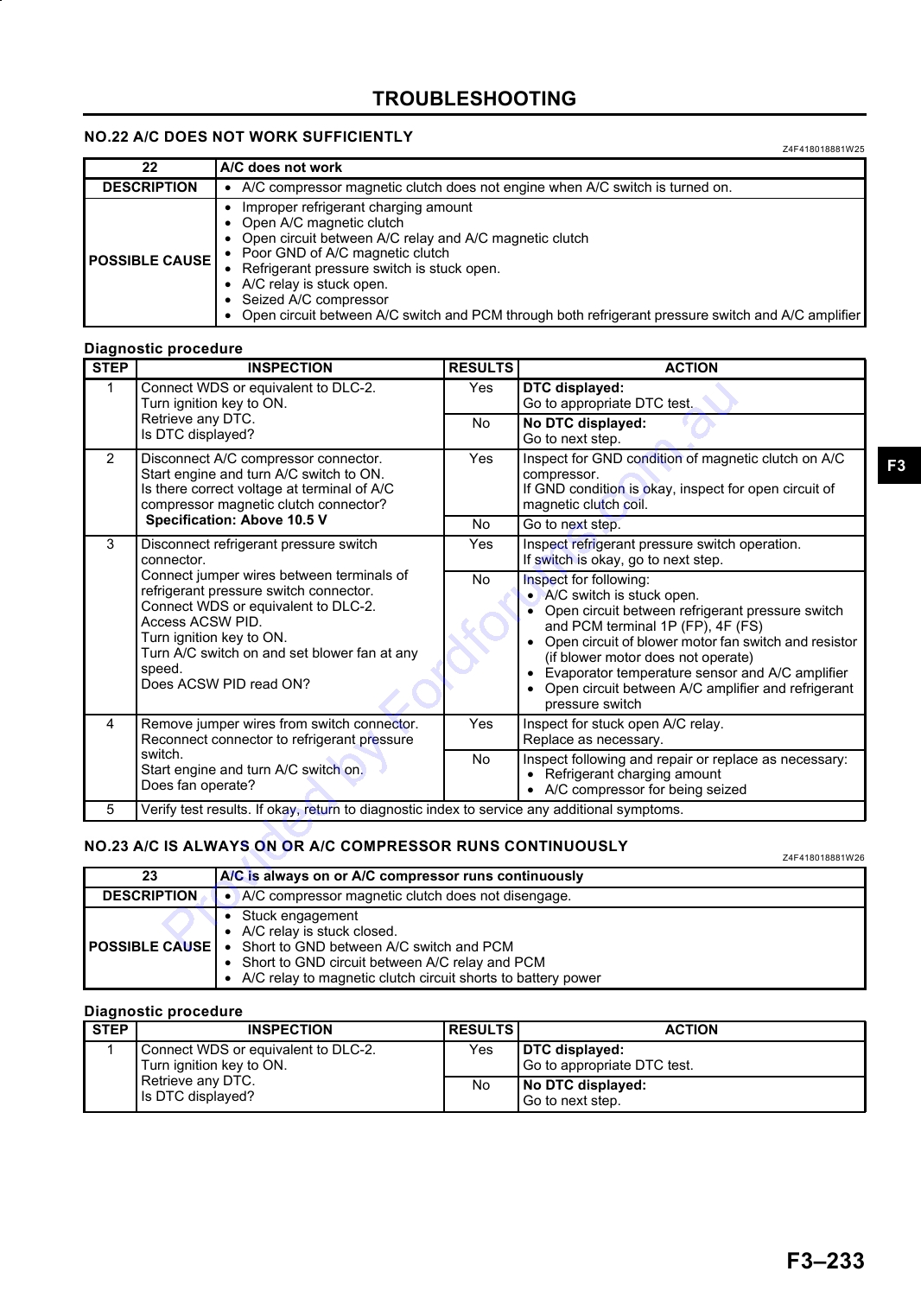
NO.22 A/C DOES NOT WORK
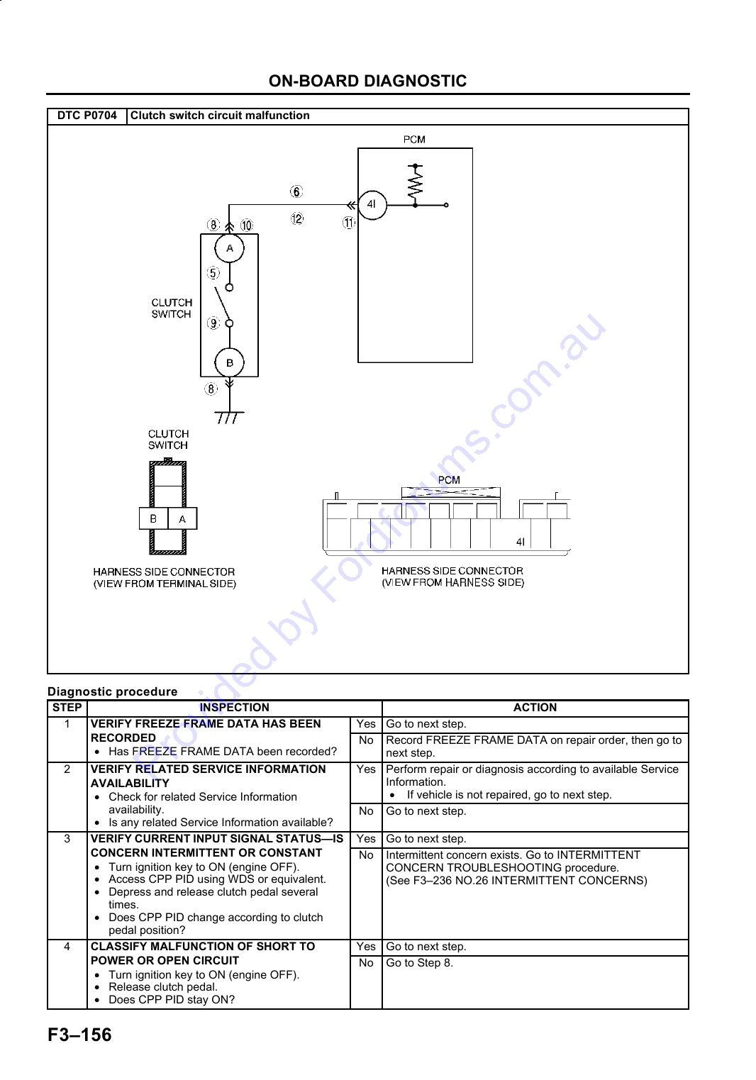
DTC P0704 (FS) ............................................ F3-155
SUFFICIENTLY........................................... F3-233
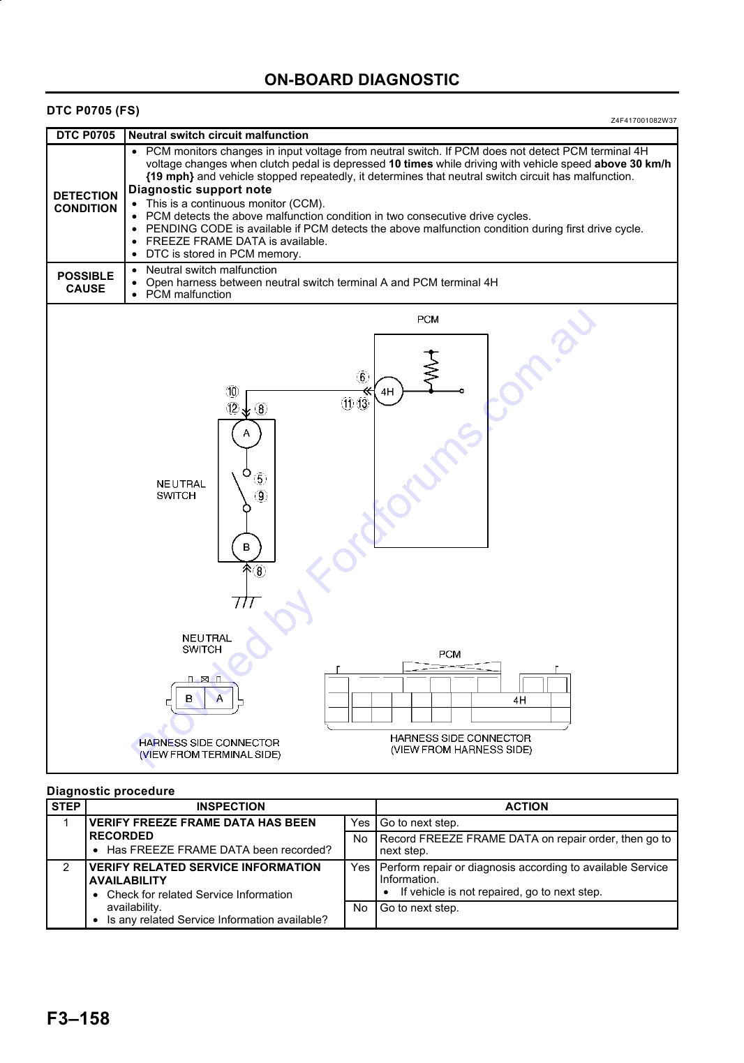
DTC P0705 (FS) ............................................ F3-158
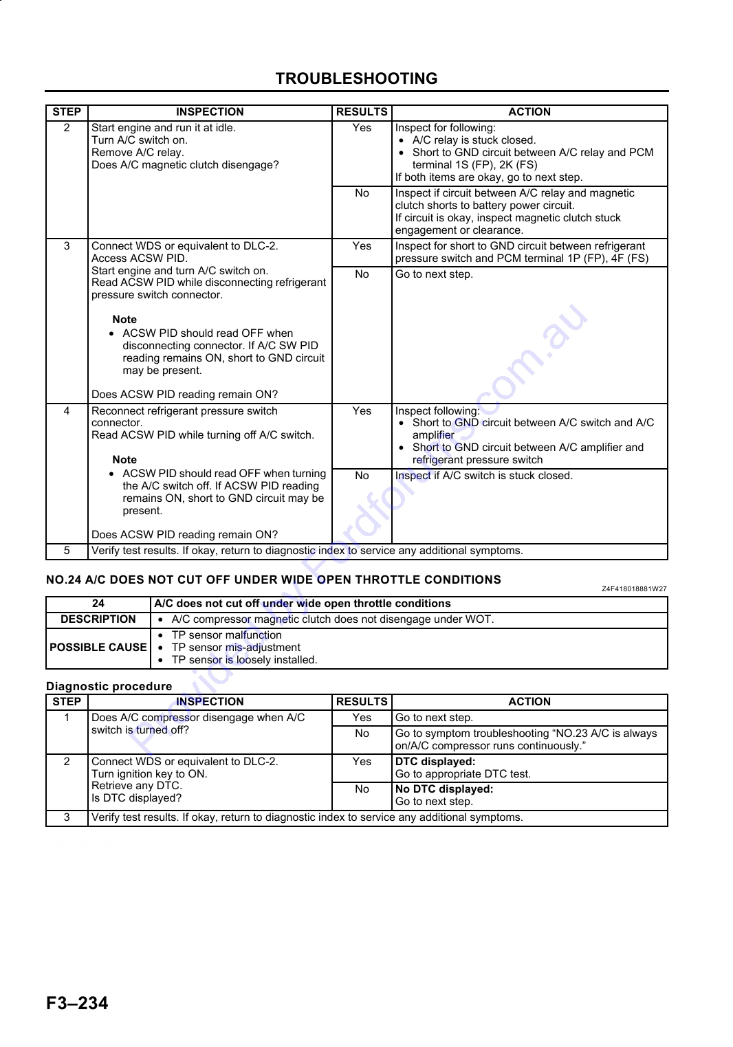
NO.23 A/C IS ALWAYS ON OR A/C
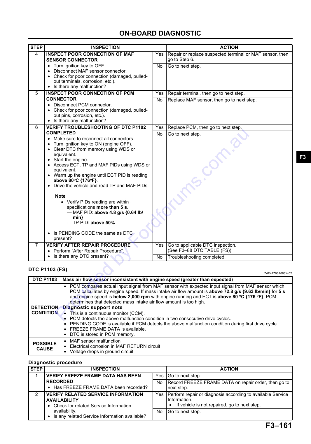
DTC P1102 (FS) ............................................ F3-160
COMPRESSOR RUNS CONTINUOUSLY . F3-233
DTC P1103 (FS) ............................................ F3-161
NO.24 A/C DOES NOT CUT OFF UNDER
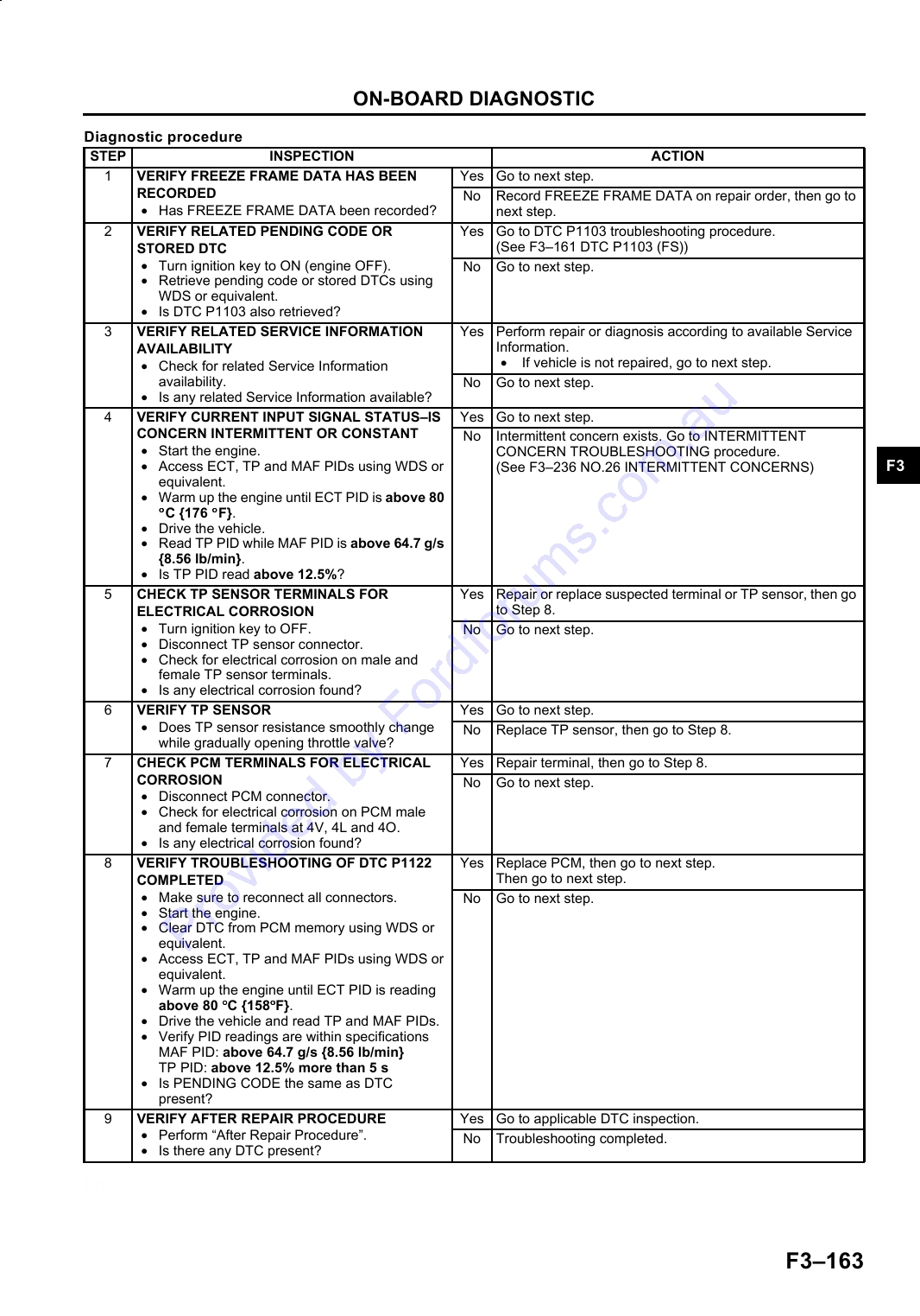
DTC P1122 (FS) ............................................ F3-162
WIDE OPEN THROTTLE CONDITIONS .... F3-234
DTC P1123 (FS) ............................................ F3-164
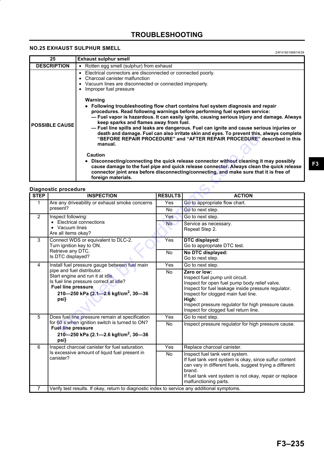
NO.25 EXHAUST SULPHUR SMELL ............ F3-235
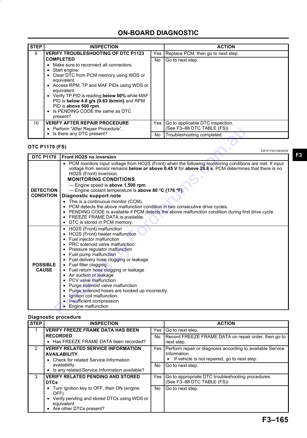
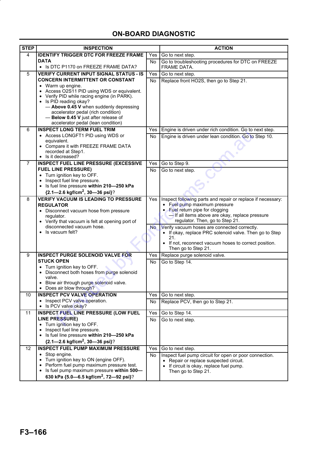
DTC P1170 (FS) ............................................ F3-165
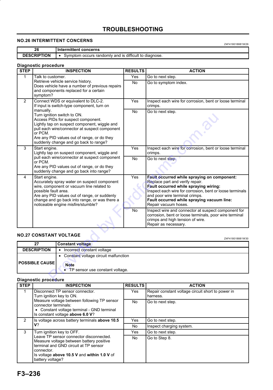
NO.26 INTERMITTENT CONCERNS ............ F3-236
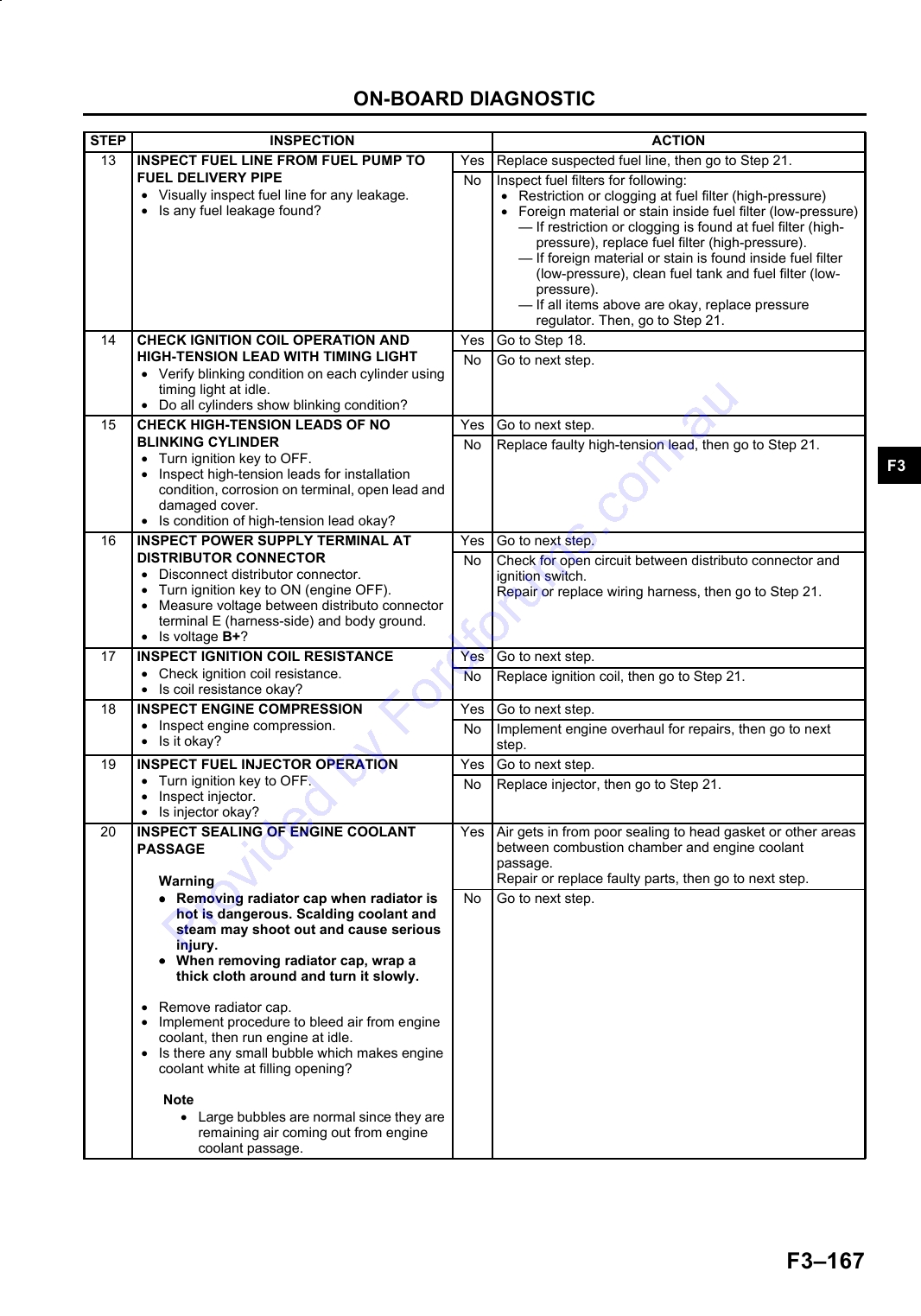
DTC P1250 (FS) ............................................ F3-168
NO.27 CONSTANT VOLTAGE ...................... F3-236
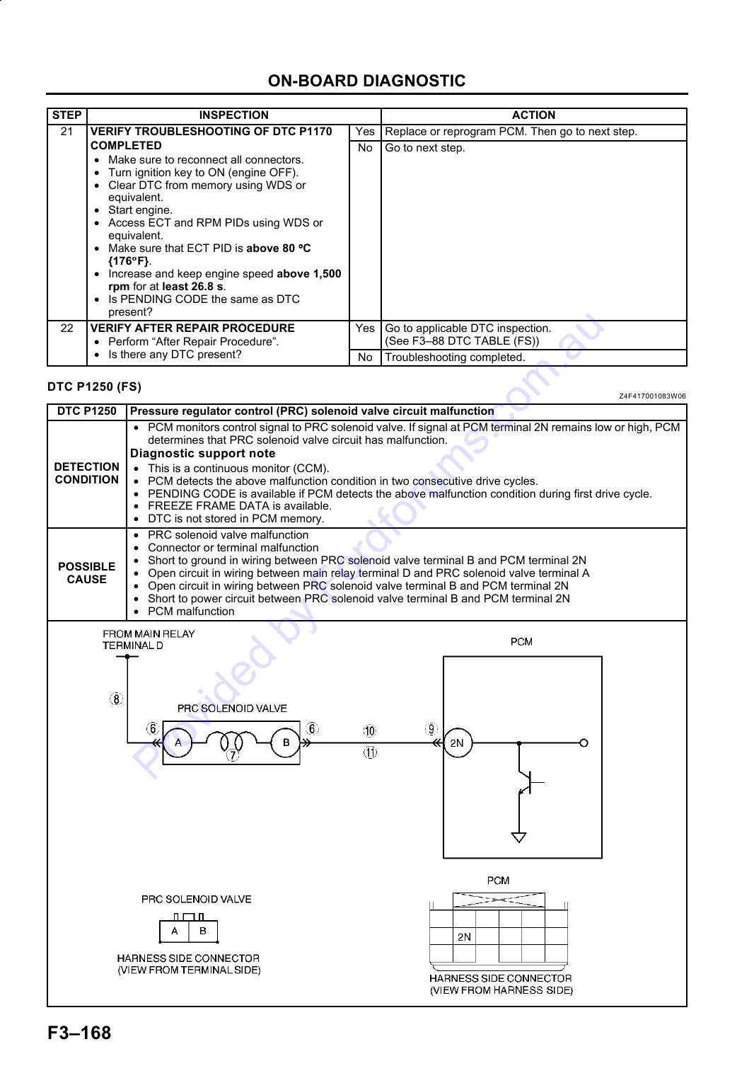
DTC P1345 (FS) ............................................ F3-170
ENGINE DIAGNOSTIC INSPECTION ........... F3-238
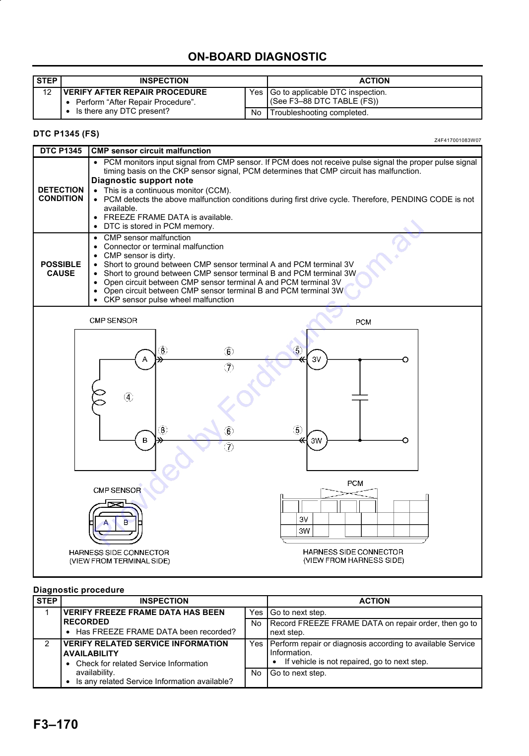
DTC P1496 (FS) ............................................ F3-172
ENGINE SYSTEM INSPECTION................... F3-240
DTC P1497 (FS) ............................................ F3-174
DTC P1498 (FS) ............................................ F3-176
DTC P1499 (FS) ............................................ F3-178
DTC P1504 (FS) ............................................ F3-180
DTC P1523 (FS) ............................................ F3-182
DTC P1562 (FS) ............................................ F3-184
DTC P1602 (FS) ............................................ F3-185
DTC P1603 (FS) ............................................ F3-188
DTC P1604 (FS) ............................................ F3-188
DTC P1608 (FS) ............................................ F3-189
DTC P1621 (FS) ............................................ F3-189
DTC P1622 (FS) ............................................ F3-190
DTC P1623 (FS) ............................................ F3-190
DTC P1624 (FS) ............................................ F3-191
DTC P1631 (FS) ............................................ F3-191
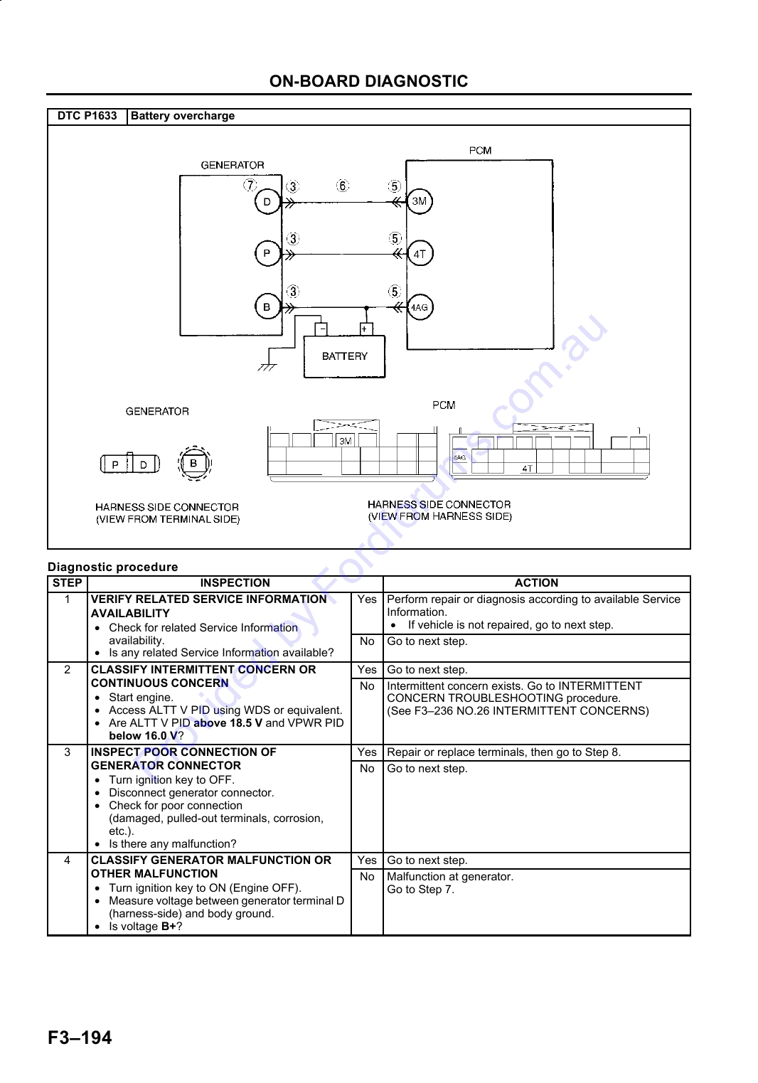
DTC P1633 (FS) ............................................ F3-193
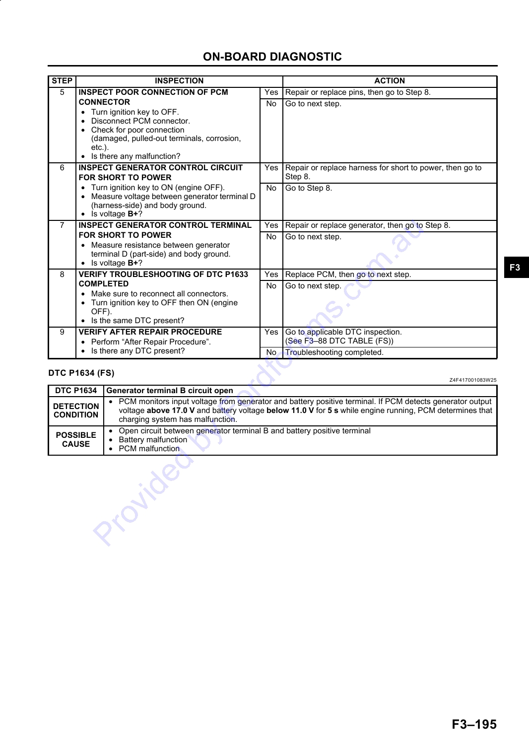
DTC P1634 (FS) ............................................ F3-195
F32
OUTLINE
OUTLINE
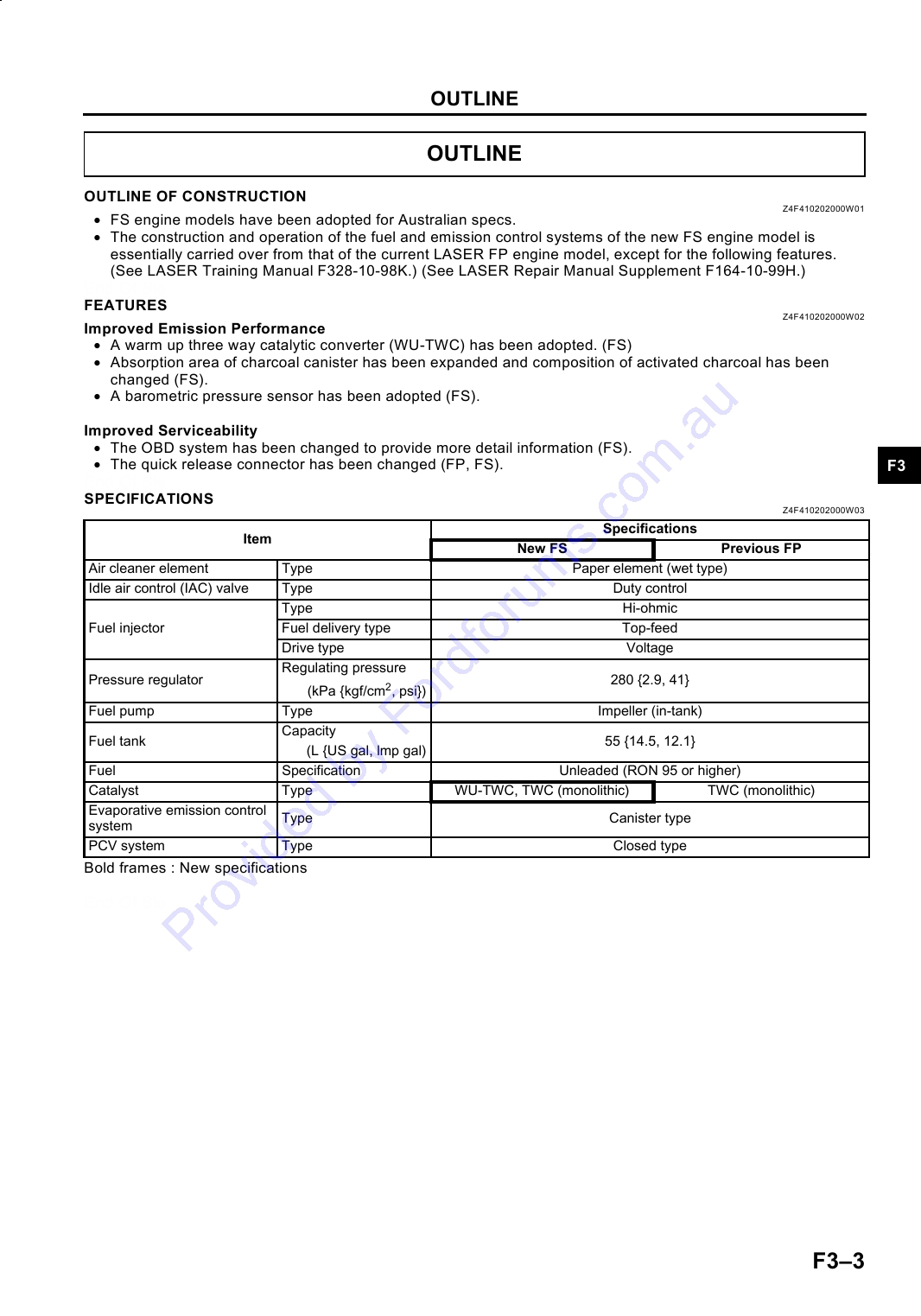
OUTLINE OF CONSTRUCTION
Z4F410202000W01
· FS engine models have been adopted for Australian specs.
· The construction and operation of the fuel and emission control systems of the new FS engine model is
essentially carried over from that of the current LASER FP engine model, except for the following features.
(See LASER Training Manual F328-10-98K.) (See LASER Repair Manual Supplement F164-10-99H.)
End Of Sie
FEATURES
Z4F410202000W02
Improved Emission Performance
· A warm up three way catalytic converter (WU-TWC) has been adopted. (FS)
· Absorption area of charcoal canister has been expanded and composition of activated charcoal has been
changed (FS).
· A barometric pressure sensor has been adopted (FS).
Improved Serviceability
· The OBD system has been changed to provide more detail information (FS).
· The quick release connector has been changed (FP, FS).
F3
End Of Sie
SPECIFICATIONS
Z4F410202000W03
Specifications
Item
New FS
Previous FP
Air cleaner element
Type
Paper element (wet type)
Idle air control (IAC) valve
Type
Duty control
Type
Hi-ohmic
Fuel injector
Fuel delivery type
Top-feed
Drive type
Voltage
Regulating pressure
Pressure regulator
280 {2.9, 41}
(kPa {kgf/cm2, psi})
Fuel pump
Type
Impeller (in-tank)
Capacity
Fuel tank
55 {14.5, 12.1}
(L {US gal, lmp gal)
Fuel
Specification
Unleaded (RON 95 or higher)
Catalyst
Type
WU-TWC, TWC (monolithic)
TWC (monolithic)
Evaporative emission control
Type
Canister type
system
PCV system
Type
Closed type
Bold frames : New specifications
End Of Sie
F33
OUTLINE
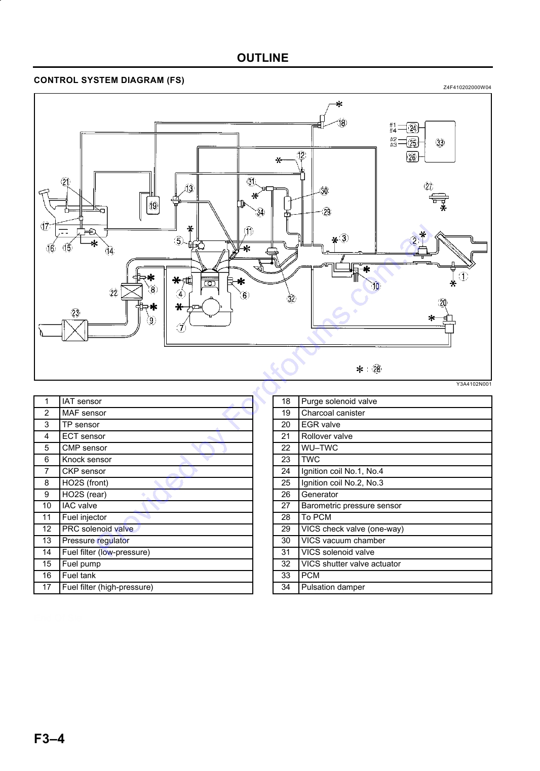
CONTROL SYSTEM DIAGRAM (FS)
Z4F410202000W04
Y3A4102N001
.
1
IAT sensor
18
Purge solenoid valve
2
MAF sensor
19
Charcoal canister
3
TP sensor
20
EGR valve
4
ECT sensor
21
Rollover valve
5
CMP sensor
22
WUTWC
6
Knock sensor
23
TWC
7
CKP sensor
24
Ignition coil No.1, No.4
8
HO2S (front)
25
Ignition coil No.2, No.3
9
HO2S (rear)
26
Generator
10
IAC valve
27
Barometric pressure sensor
11
Fuel injector
28
To PCM
12
PRC solenoid valve
29
VICS check valve (one-way)
13
Pressure regulator
30
VICS vacuum chamber
14
Fuel filter (low-pressure)
31
VICS solenoid valve
15
Fuel pump
32
VICS shutter valve actuator
16
Fuel tank
33
PCM
17
Fuel filter (high-pressure)
34
Pulsation damper
End Of Sie
F34
OUTLINE
F3
F35
OUTLINE
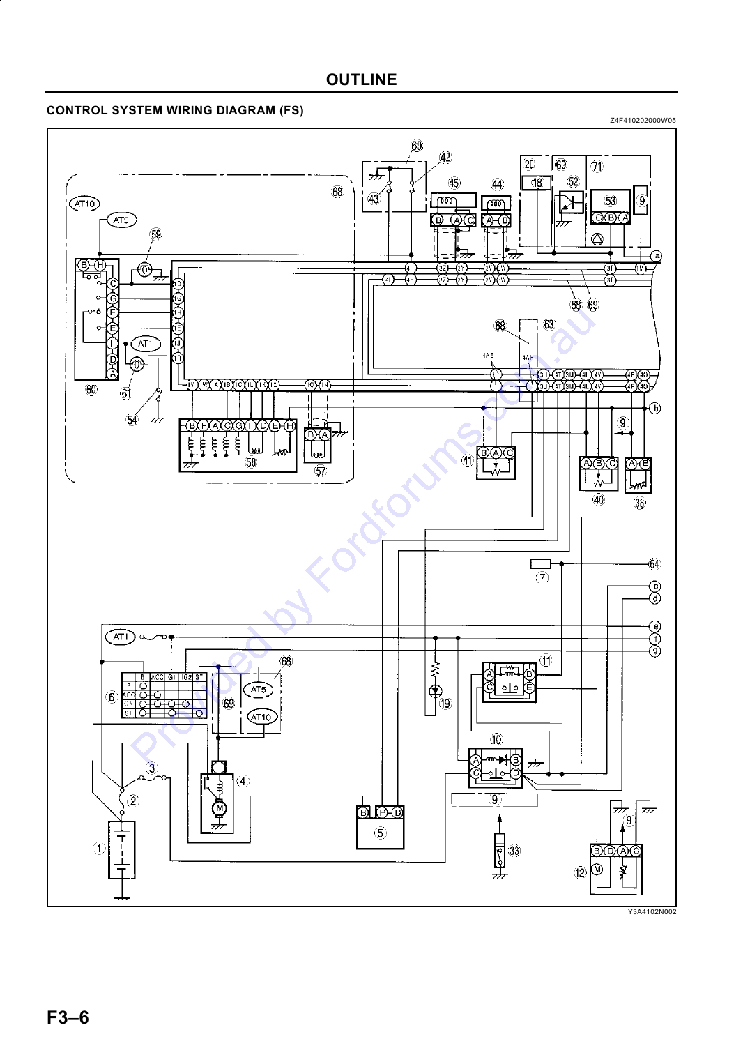
CONTROL SYSTEM WIRING DIAGRAM (FS)
Z4F410202000W05
Y3A4102N002
F36
OUTLINE
F3
Y3E4102N003
.
F37
OUTLINE
1
Battery
37
PRC solenoid valve
2
Main fuse
38
ECT sensor
3
INJ fuse
39
IAT sensor
4
Starter
40
TP sensor
5
Generator
41
Barometric pressure sensor
6
Ignition switch
42
Neutral switch
7
DLC
43
Clutch switch
8
DSC unit
44
CMP sensor
9
To instrument cluster
45
CKP sensor
10
Main relay
46
Fuel injector No.1
11
Fuel pump relay
47
Fuel injector No.2
12
Fuel pump unit
48
Fuel injector No.3
13
PSP switch
49
Fuel injector No.4
14
HO2S (rear)
50
Condenser
15
HO2S (front)
51
Ignition coil
16
EGR valve
52
VSS (integrated with instrument cluster)
17
MAF sensor
53
VSS
18
To ABS
54
Hold switch
19
Generator warning light
55
Brake light
20
For ATX model (with ABS)
56
Brake switch
21
Blower motor
57
Input/turbine speed sensor
22
VICS solenoid valve
58
EC-AT solenoid
23
Fan switch
59
Back-up light
24
A/C relay
60
TR switch
25
A/C switch
61
Hold indicator light
26
A/C amplifier
62
Knock sensor
27
Refrigerant pressure switch
63
PCM
28
A/C compressor
64
Terminal 2M in PCM
29
Condenser fan relay
65
DLC-2
30
Condenser fan motor
66
Microcomputer (DIS)
31
Cooling fan relay
67
Refrigerant pressure switch
32
Cooling fan motor
68
For ATX model
33
Oil pressure switch
69
For MTX model
34
Immobilizer unit
70
A/C equipped only
35
IAC valve
71
For ATX model (without ABS)
36
Purge solenoid valve
End Of Sie
F38
FUEL SYSTEM
FUEL SYSTEM
OUTLINE
Z4F411201006W01
· The construction and operation of the fuel systems of the face-lifted FP engine models and new FS engine
models are essentially carried over from that of the current LASER FP engine models, except for the following.
-- The quick release connector (engine room side) has been changed.
End Of Sie
STRUCTURAL VIEW
Z4F411201006W02
F3
Y3E4112N001
.
1
Pulsation damper
5
Quick release connector
2
Fuel injector
6
Fuel pump relay
3
Pressure regulator
7
To fuel tank
4
PRC solenoid valve
8
From fuel tank
End Of Sie
F39
FUEL SYSTEM
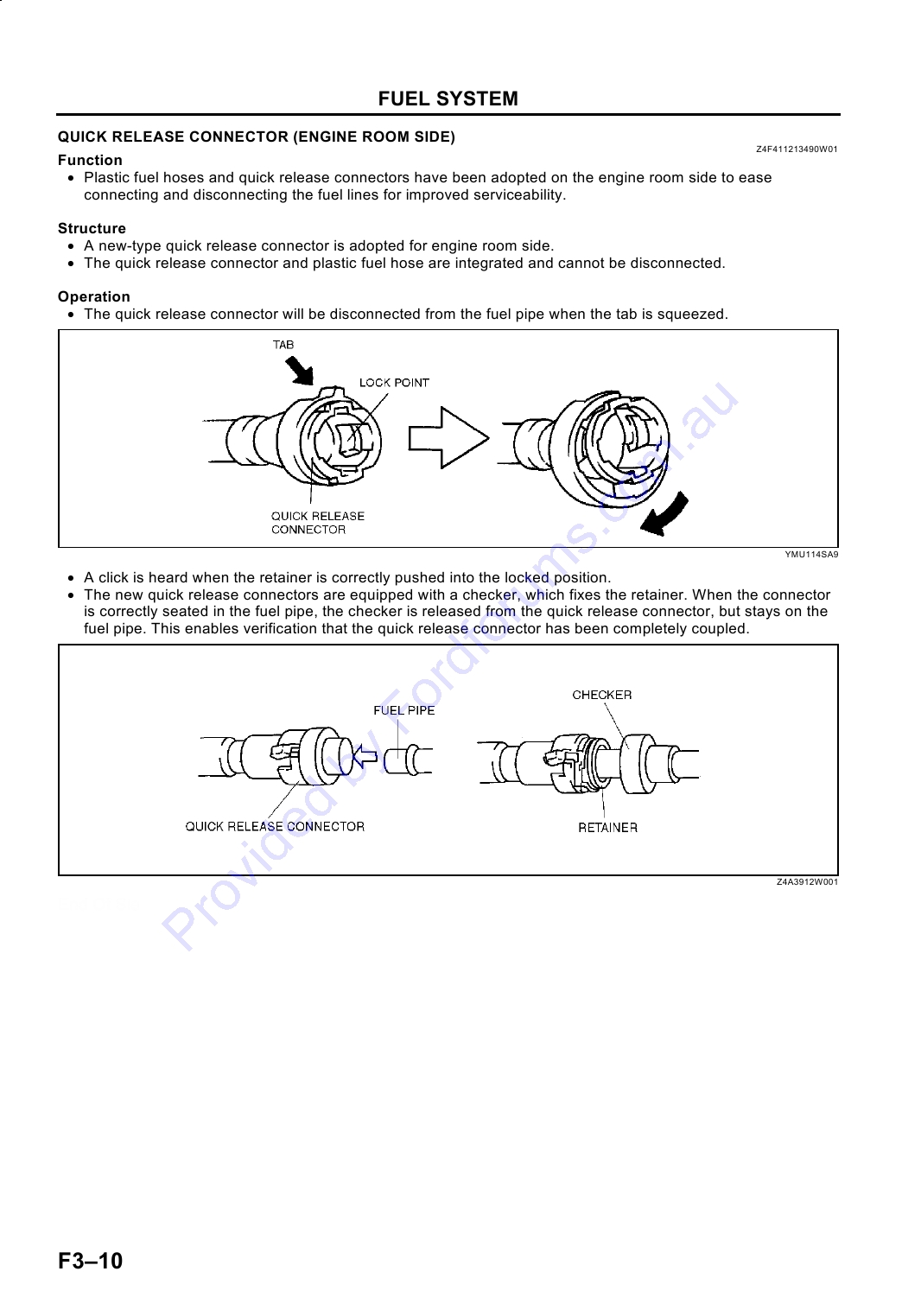
QUICK RELEASE CONNECTOR (ENGINE ROOM SIDE)
Z4F411213490W01
Function
· Plastic fuel hoses and quick release connectors have been adopted on the engine room side to ease
connecting and disconnecting the fuel lines for improved serviceability.
Structure
· A new-type quick release connector is adopted for engine room side.
· The quick release connector and plastic fuel hose are integrated and cannot be disconnected.
Operation
· The quick release connector will be disconnected from the fuel pipe when the tab is squeezed.
YMU114SA9
· A click is heard when the retainer is correctly pushed into the locked position.
· The new quick release connectors are equipped with a checker, which fixes the retainer. When the connector
is correctly seated in the fuel pipe, the checker is released from the quick release connector, but stays on the
fuel pipe. This enables verification that the quick release connector has been completely coupled.
Z4A3912W001
End Of Sie
F310
FUEL SYSTEM
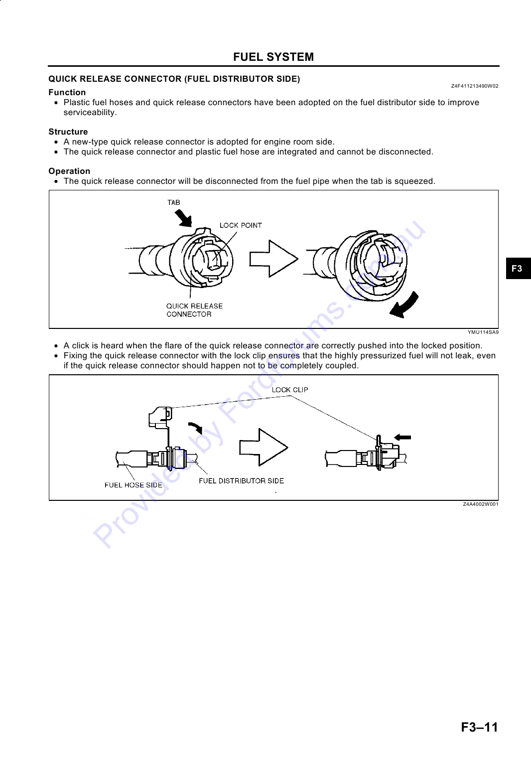
QUICK RELEASE CONNECTOR (FUEL DISTRIBUTOR SIDE)
Z4F411213490W02
Function
· Plastic fuel hoses and quick release connectors have been adopted on the fuel distributor side to improve
serviceability.
Structure
· A new-type quick release connector is adopted for engine room side.
· The quick release connector and plastic fuel hose are integrated and cannot be disconnected.
Operation
· The quick release connector will be disconnected from the fuel pipe when the tab is squeezed.
F3
YMU114SA9
· A click is heard when the flare of the quick release connector are correctly pushed into the locked position.
· Fixing the quick release connector with the lock clip ensures that the highly pressurized fuel will not leak, even
if the quick release connector should happen not to be completely coupled.
Z4A4002W001
End Of Sie
F311
EMISSION SYSTEM
EMISSION SYSTEM
OUTLINE
Z4F411601007W01
· The construction and operation of the emission systems of the new FS engine models is essentially carried
over from that of the cuurent LASER FP engine models, except for the following.
-- The warm up three way catalytic converter (WU-TWC) has been adopted between the exhaust manifold
and front pipe to improve emission performance.
-- Absorption area of charcoal canister has been expended and composition of activated charcoal has been
changed.
End Of Sie
STRUCTURAL VIEW (FS)
Z4F411601007W02
Engine Room Side
Y3A4116N001
.
1
Charcoal canister
4
PCV valve
2
Purge solenoid valve
5
WU-TWC
3
EGR valve
End Of Sie
F312
EMISSION SYSTEM
CHARCOAL CANISTER (FS)
Z4F411613970W01
· A U-flow type charcoal canister whose internal flow shaped like a U has been adopted.
YPE3916W001
· The incorporation of this type of charcoal expands the area of absorption, increasing the amount of fuel
evaporative emission particulate absorption. Absorption efficiency enhanced activated charcoal has also been
adopted.
End Of Sie
F3
WARM UP THREE WAY CATALYTIC CONVERTER (WU-TWC) (FS)
Z4F411620505W01
· The WU-TWC warms up and energizes quickly after the engine starts, so exhaust gas conversion to less
harmful emissions starts earlier at cold engine start up.
End Of Sie
F313
CONTROL SYSTEM
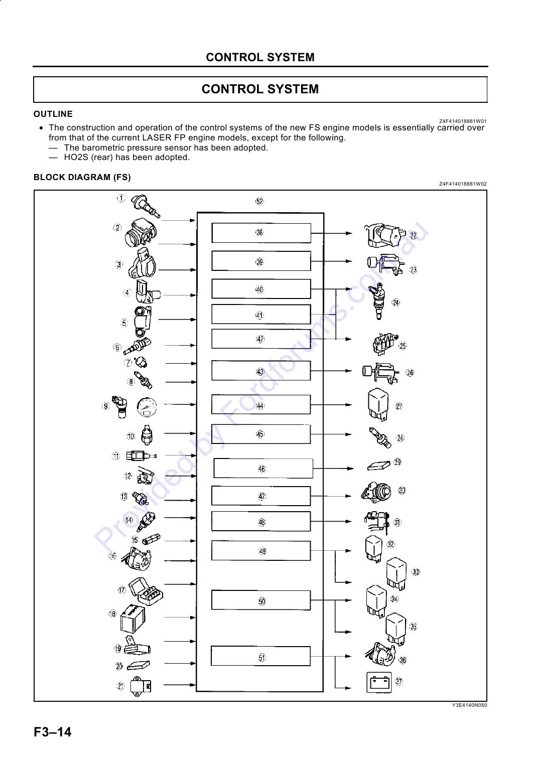
CONTROL SYSTEM
OUTLINE
Z4F414018881W01
· The construction and operation of the control systems of the new FS engine models is essentially carried over
from that of the current LASER FP engine models, except for the following.
-- The barometric pressure sensor has been adopted.
-- HO2S (rear) has been adopted.
End Of Sie
BLOCK DIAGRAM (FS)
Z4F414018881W02
Y3E4140N050
.
F314
CONTROL SYSTEM
1
IAT sensor
27
Fuel pump relay
2
MAF sensor
28
HO2S heater (front and rear)
3
TP sensor
29
ABS/TCS HU/CM or DSC
4
CMP sensor
30
EGR valve
5
CKP sensor
31
Purge solenoid valve
6
ECT sensor
32
A/C relay (with A/C)
7
Knock sensor
33
Condenser fan relay (MTX)
8
HO2S (front and rear)
34
Cooling fan relay
9
VSS
35
Condenser fan relay (ATX)
10
Clutch switch (MTX)
36
Generator (terminal D: field coil control)
11
Neutral switch (MTX)
Generator warning light (integrated with instrument
37
cluster)
12
TR switch (ATX)
38
IAC (idle air control) system
13
PSP switch
39
VICS (variable inertia charging system)
14
Brake switch
40
Fuel injection control
A/C switch, refrigerant pressure switch (high, low
15
41
Immobilizer system
pressure) (with A/C)
42
ESA (electronic spark advance) control
16
Generator (terminal P: output voltage)
F3
43
PRC (pressure regulator control)
17
DLC (terminal TEN)
44
Fuel pump control
18
Battery
45
HO2S control
19
Immobilizer unit
46
Traction control
20
ABS/TCS HU/CM or DSC
47
EGR control
21
Barometric Pressure sensor
48
Purge control
22
IAC valve
49
A/C cut-off control
23
VICS solenoid valve
50
Electrical fan control
24
Fuel injectors
51
Generator control
25
Ignition coil
52
PCM
26
PRC solenoid valve
End Of Sie
F315
CONTROL SYSTEM
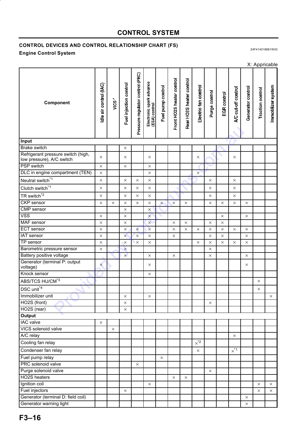
CONTROL DEVICES AND CONTROL RELATIONSHIP CHART (FS)
Z4F414018881W03
Engine Control System
X: Appricable
Component
Input
×
Brake switch
Refrigerant pressure switch (high,
×
×
×
×
×
low pressure), A/C switch
×
×
×
PSP switch
×
×
×
DLC in engine compartment (TEN)
×
×
×
×
×
×
Neutral switch*1
×
×
×
×
×
×
Clutch switch*1
×
×
×
×
×
×
TR switch*2
×
×
×
×
×
×
×
×
×
×
×
×
CKP sensor
×
×
CMP sensor
×
×
×
×
×
VSS
×
×
×
×
×
×
×
MAF sensor
×
×
×
×
×
×
×
×
×
×
×
ECT sensor
×
×
×
×
×
×
×
×
IAT sensor
×
×
×
×
×
×
×
×
×
TP sensor
×
×
×
Barometric pressure sensor
×
×
×
×
×
Battery positive voltage
Generator (terminal P: output
×
×
×
voltage)
×
Knock sensor
×
ABS/TCS HU/CM*3
×
DSC unit*4
×
×
×
Immobilizer unit
×
×
HO2S (front)
×
HO2S (rear)
Output
×
IAC valve
×
VICS solenoid valve
×
A/C relay
×*2
Cooling fan relay
×
×*1
Condenser fan relay
×
Fuel pump relay
×
PRC solenoid valve
×
Purge solenoid valve
×
×
HO2S heaters
×
×
×
Ignition coil
×
×
×
Fuel injectors
×
Generator (terminal D: field coil)
×
Generator warning light
F316
CONTROL SYSTEM
Component
×
ABS/TCS HU/CM*3
×
DSC unit*4
*1
: For MTX model
*2
: For ATX model
*3
: With TCS
*4
: With DSC
F3
Monitoring System
X: Appricable
Component
Input
×
×
×
×
×
CKP sensor
×
×
×
×
×
CMP sensor
×
×
×
×
VSS
×
×
×
×
×
MAF sensor
×
×
×
×
×
ECT sensor
×
×
×
×
IAT sensor
×
×
×
×
TP sensor
×
×
×
HO2S (rear)
×
×
×
×
HO2S (front)
Output
×
×
×
×
×
DLC-2 in drivers compartment (Terminal KLN)
×
×
Purge solenoid valve
×
Fuel injectors
End Of Sie
F317
CONTROL SYSTEM
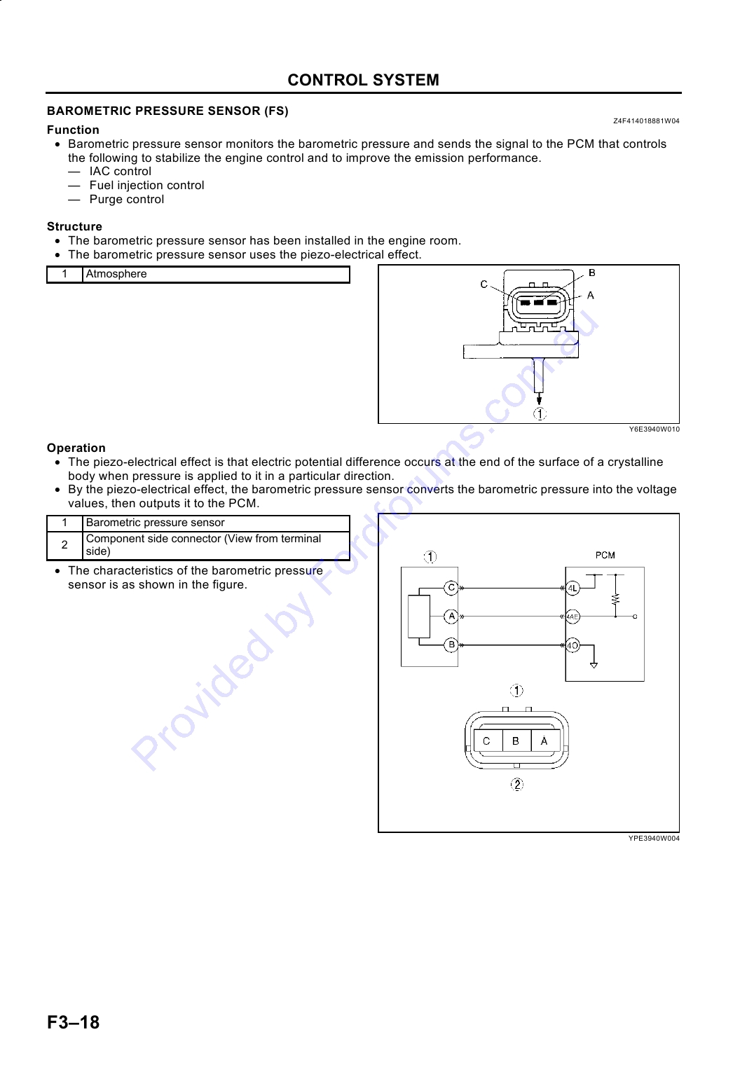
BAROMETRIC PRESSURE SENSOR (FS)
Z4F414018881W04
Function
· Barometric pressure sensor monitors the barometric pressure and sends the signal to the PCM that controls
the following to stabilize the engine control and to improve the emission performance.
-- IAC control
-- Fuel injection control
-- Purge control
Structure
· The barometric pressure sensor has been installed in the engine room.
· The barometric pressure sensor uses the piezo-electrical effect.
.
1
Atmosphere
Y6E3940W010
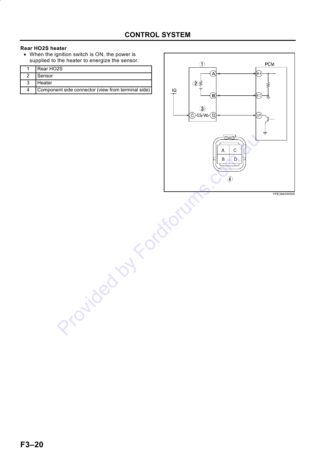
Operation
· The piezo-electrical effect is that electric potential difference occurs at the end of the surface of a crystalline
body when pressure is applied to it in a particular direction.
· By the piezo-electrical effect, the barometric pressure sensor converts the barometric pressure into the voltage
values, then outputs it to the PCM.
.
1
Barometric pressure sensor
Component side connector (View from terminal
2
side)
· The characteristics of the barometric pressure
sensor is as shown in the figure.
YPE3940W004
F318
CONTROL SYSTEM
.
1
Output voltage
2
Atmospheric pressure
Y6E3940W003
End Of Sie
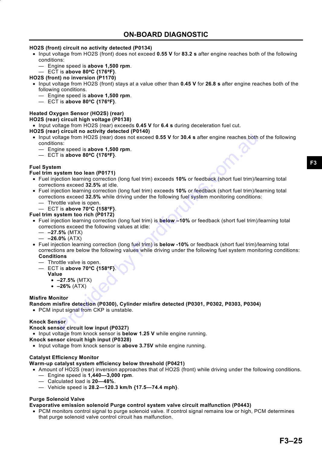
REAR HEATED OXYGEN SENSOR (HO2S) (FS)
Z4F414018861W01
Function
· Rear HO2S monitors the condition of the WU-TWC.
Structure
· Rear HO2S is installed between the WU-TWC and the TWC (downstream of the WU-TWC).
· Rear HO2S has the heater for the stable signal detection.
F3
Operation
Rear HO2S
· The characteristic of the HO2S is as shown in the
figure. Its electromotive force changes depending
on the amount of oxygen.
.
1
Electromotive force
2
Air/fuel ratio
3
High
4
Low
5
Rich
6
Lean
· Rear HO2S is used for monitoring the WU-TWC
Y6E3940W004
efficiency based on oxygen storage capacity.
· If the WU-TWC has high oxygen storage, the rear
HO2S switching frequency slows compared to
that of the front HO2S.
.
1
Voltage
2
Time
3
Low oxygen
4
High oxygen
Y6E3940W005
· If the WU-TWC deteriorates and oxygen storage
capability declines, the rear HO2S frequency
switches more rapidly.
.
1
Voltage
2
Time
3
Low oxygen
4
High oxygen
Y6E3940W006
F319
CONTROL SYSTEM
Rear HO2S heater
· When the ignition switch is ON, the power is
supplied to the heater to energize the sensor.
.
1
Rear HO2S
2
Sensor
3
Heater
4
Component side connector (view from terminal side)
YPE3940W005
End Of Sie
F320
ON-BOARD DIAGNOSTIC
ON-BOARD DIAGNOSTIC
OUTLINE
Z4F417018881W01
· The construction and operation of the control systems of the new FS engine models is essentially carried over
from that of the previous LASER FP engine models, except for the following. (See LASER Training Manual
F328-10-98K.)
-- DTCs PID monitoring items, and simulation items have been added to match the EURO-OBD regulations
without malfunction indicator (MI). For the detailed information of the EURO-OBD regulations, refer to the
"OBD Training Manual (3345-1*-00B)."
End Of Sie
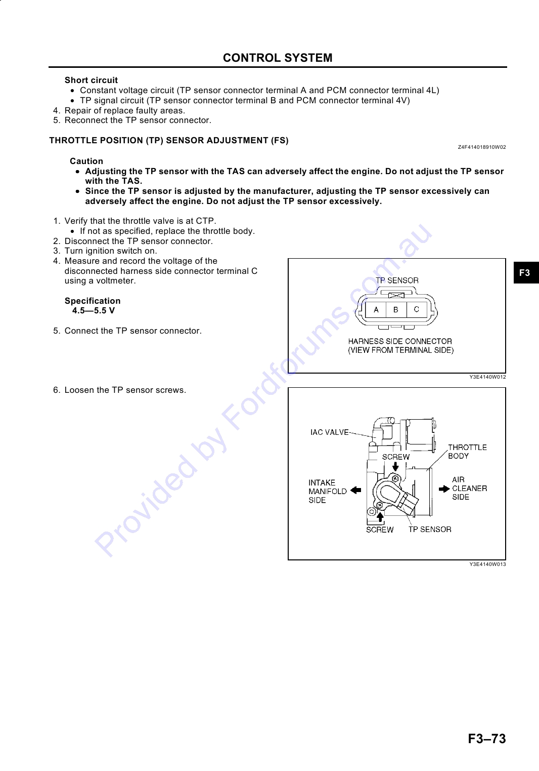
DIAGNOSTIC TEST MODE (FS)
Z4F417018881W02
· The following diagnostic test modes have been available to match the EURO-OBD regulations.
Diagnostic test mode
Item
Mode 01
Sending diagnostic data (PID data monitor/on-board system readiness test)
Mode 02
Sending freeze frame data
Mode 03
Sending emission-related malfunction code (diagnostic trouble code: DTC)
F3
Mode 04
Clearing/resetting emission-related malfunction information
Mode 05
Sending oxygen sensor monitor test results
Mode 06
Sending intermittent monitoring system test results (diagnostic monitoring test result: DMTR)
Mode 07
Sending continuous monitoring system test results (pending code)
Sending Diagnostic Data (Mode 01)
PID data monitor
· The PID monitoring items are shown in the table.
PID data monitor table
Monitor item
Full names
Condition/unit
DTC_CNT
Diagnostic trouble code counter
°C, °F
ECT
Engine coolant temperature
FUELSYS
Fuel system loop status
Refer to table below.
°C, °F
IAT
Intake air temperature
LOAD
Engine load calculated value
%
LONGFT1
Long fuel trim
%
MAF
Mass air flow
g/s, lb/m
MIL
Malfunction indicator
ON/OFF
MIL DIS
Distance travelled while MI is activated
km, miles
O2S11
HO2S (Heated oxygen sensor) (Front)
V
O2S12
HO2S (Heated oxygen sensor) (Rear)
V
RPM
Engine speed
rpm
SHRFT1
Short fuel trim
%
SPARKADV
Spark advance
BTDC
TP
Throttle position
%
VSS
Vehicle speed
km/h, mph
Meaning of FUELSYS
Display
Meaning
-NA-
Not applicable
OL
Feedback stops: Engine coolant temperature is lower than the determined feedback zone.
CL
Feedback operating: HO2S being used for feedback is okay.
OLDrive
Feedback stops: Open loop due to driving condition.
OLFault
Feedback stops: Open loop due to detected system fault.
CLFault
Feedback operating: Malfunction occurred in HO2S (rear) system.
F321
ON-BOARD DIAGNOSTIC
On-board system readiness test
· The items supported by the on-board system readiness test are shown below.
Continuous monitoring system
-- Misfire monitoring
-- Fuel system monitoring
-- Comprehensive component monitoring (CCM)
Intermittent monitoring system
-- Catalyst monitoring
-- HO2S monitoring
-- HO2S heater monitoring
Sending Freeze Frame Data (FFD) (Mode 02)
· The FFDs are shown in the table.
FFD monitor table
Monitor item
Full names
Condition/unit
Diagnostic trouble code (DTC)
°C, °F
ECT
Engine coolant temperature
FUELSYS
Fuel system loop status
OPEN: NONF/B, CLOSE: F/B
LOAD
Engine load calculated value
%
LONGFT1
Long fuel trim
%
RPM
Engine speed
rpm
SHRFT1
Short fuel trim
%
VSS
Vehicle speed
km/h, mph
Sending Emission-related Malfunction code (DTC)
· The DTCs are shown in the table.
DTC table
×: Applied
Hold
Memory
DTC
Condition
indicator
DC
Monitor item
function
light
×
P0031
HO2S (front) heater circuit low input
--
2
HO2S heater
×
P0032
HO2S (front) heater circuit high input
--
2
HO2S heater
×
P0037
HO2S (rear) heater circuit low input
--
2
HO2S heater
×
P0038
HO2S (rear) heater circuit high input
--
2
HO2S heater
×
P0102
MAF circuit low input
--
1
CCM
×
P0103
MAF circuit high input
--
1
CCM
×
P0107
BARO circuit low input
--
1
CCM
×
P0108
BARO circuit high input
--
1
CCM
×
P0111
IAT circuit performance problem
--
2
CCM
×
P0112
IAT circuit low input
--
1
CCM
×
P0113
IAT circuit high input
--
1
CCM
×
P0117
ECT circuit low input
--
1
CCM
×
P0118
ECT circuit high input
--
1
CCM
×
P0122
TP circuit low input
Flashes
1
CCM
×
P0123
TP circuit high input
Flashes
1
CCM
×
P0125
Excessive time to enter closed loop fuel control
--
2
CCM
×
P0130
HO2S (front) circuit malfunction
--
2
HO2S
×
P0134
HO2S (front) circuit no activity detected
--
2
CCM
×
P0138
HO2S (rear) circuit high voltage
--
2
CCM
×
P0140
HO2S (rear) circuit no activity detected
--
2
CCM
×
P0171
Fuel trim system too lean
--
2
Fuel
×
P0172
Fuel trim system too rich
--
2
Fuel
×
P0300
Random misfire detection
--
1 or 2
Misfire
×
P0301
Cylinder No.1 misfire detected
--
1 or 2
Misfire
×
P0302
Cylinder No.2 misfire detected
--
1 or 2
Misfire
×
P0303
Cylinder No.3 misfire detected
--
1 or 2
Misfire
×
P0304
Cylinder No.4 misfire detected
--
1 or 2
Misfire
×
P0327
Knock sensor circuit low input
--
1
CCM
F322
ON-BOARD DIAGNOSTIC
Hold
Memory
DTC
Condition
indicator
DC
Monitor item
function
light
×
P0328
Knock sensor circuit high input
--
1
CCM
×
P0335
CKP sensor circuit malfunction
--
1
CCM
×
P0421
Warm-up catalyst system efficiency below threshold
--
2
Catalyst
Evaporative emission solenoid system purge control valve
×
P0443
--
2
CCM
circuit malfunction
×
P0500
Vehicle speed sensor (VSS) circuit malfunction (MTX)
--
2
CCM
×
P0506
Idle control system RPM lower than expected
--
2
CCM
×
P0507
Idle control system RPM higher than expected
--
2
CCM
×
P0550
PSP switch circuit malfunction
--
2
CCM
×
P0605
PCM read only memory (ROM) test error
--
1
Other
×
P0703
Brake switch input malfunction
--
2
CCM
×
P0704
Clutch switch circuit malfunction (MTX)
--
2
CCM
×
P0705
Neutral switch circuit malfunction (MTX)
--
2
CCM
MAF sensor value inconsistent with TP sensor (lower than
×
P1102
--
2
CCM
expected)
F3
MAF sensor value inconsistent with engine speed (greater
×
P1103
--
2
CCM
than expected)
×
P1122
Throttle position stuck closed (lower than expected)
--
2
CCM
×
P1123
Throttle position stuck open (higher than expected)
--
2
CCM
×
P1170
HO2S (front) no inversion
--
2
CCM
P1250
Pressure regulator control (PRC) valve circuit malfunction
--
1
CCM
--
×
P1345
CMP sensor circuit malfunction
--
1
CCM
×
P1496
EGR valve stepping motor coil 1 open or short
--
2
CCM
×
P1497
EGR valve stepping motor coil 2 open or short
--
2
CCM
×
P1498
EGR valve stepping motor coil 3 open or short
--
2
CCM
×
P1499
EGR valve stepping motor coil 4 open or short
--
2
CCM
×
P1504
IAC valve circuit malfunction
--
1
CCM
P1523
VICS solenoid valve circuit malfunction
--
1
Other
--
×
P1562
PCM +BB voltage low
--
1
CCM
×
P1602
Immobilizer unit-PCM communication error
--
--
Other
×
P1603
Key ID number unregistered in PCM
--
--
Other
×
P1604
Code word unregistered in PCM
--
--
Other
P1608
PCM internal circuit mulfunction
--
1
Other
--
×
P1621
Code words do not match after engine cranking
--
--
Other
×
P1622
Key ID number mismatch
--
--
Other
×
P1623
Cord word or key ID number read/write error in PCM
--
--
Other
×
P1624
Immobilizer system communication counter=0
--
--
Other
×
P1627
PCM/TCS line-communication error
--
1
Other
×
P1631
Generator output voltage signal no electricity
--
1
Other
×
P1633
Battery overcharge
--
1
Other
×
P1634
Generator terminal B circuit open
--
1
Other
Sending Intermittent Monitoring System Test Results (Mode 06)
· The items supported by the sending intermittent monitoring system are shown in the table.
TEST ID
Description
Related system
10:01:11
HO2S (front) inversion cycles
10:02:11
HO2S (front) lean-to-rich response time
10:03:11
HO2S (front) rich-to-lean response time
10:04:01
HO2S (front) rich/lean inversion voltage
HO2S
10:04:02
HO2S (rear) inversion voltage
10:05:01
HO2S (front) lean threshold voltage
10:06:01
HO2S (front) rich threshold voltage
10:11:11
HO2S (front and rear) switching time ratio
TWC
F323
ON-BOARD DIAGNOSTIC
End Of Sie
DTC (FS)
Z4F417018881W03
· The DTCs shown below have been added, or changed for the detection logic or condition.
Heated Oxygen Sensor (HO2S) Heater
HO2S heater (front) circuit low input (P0031)
· PCM terminal (3J) voltage is low when HO2S heater (front) condition is OFF.
HO2S heater (front) circuit high input (P0032)
· PCM terminal (3J) voltage is high when HO2S heater (front) condition is ON.
HO2S heater (rear) circuit low input (P0037)
· PCM terminal (3P) voltage is low when HO2S heater (rear) condition is OFF.
HO2S heater (rear) circuit high input (P0038)
· PCM terminal (3P) voltage is high when HO2S heater (rear) condition is ON.
Barometric Pressure Sensor
BARO circuit low input (P0107)
· Input voltage from barometric pressure sensor is below 1.99 V while engine running.
BARO circuit high input (P0108)
· Input voltage from barometric pressure sensor is above 4.43 V while engine running.
Intake Air Temperature (IAT) Sensor
IAT circuit performance problem (P0111)
· Intake air temperature is higher than engine coolant temperature by 40°C {104°F} while engine running.
Engine Coolant Temperature (ECT) Sensor
Excessive time to enter closed loop fuel control (P0125)
· ECT does not rise above specified temperature after engine is started and a certain period of time has passed.
Heated Oxygen Sensor (HO2S) (front)
HO2S (front) circuit malfunction (P0130)
· HO2S (front) sends any of the following HO2S (front) signals while driving under the following conditions:
Conditions
-- Engine speed is 1,410--4,000 rpm.
-- Calculated load is 15--59% [MTX] 18--59% [ATX] (depending on engine speed).
-- ECT is above 10°C {14°F}.
-- Vehicle speed is over 3.8 km/h {2.4 mph}.
MTX
ATX
A
More than 0.51 s
More than 0.53 s
B
More than 0.56 s
More than 0.42 s
Y6E3970W001
.
1
Oxygen sensor output signal
4
Oxygen sensor lean-to-rich response time
2
Rich
5
Oxygen sensor rich-to-lean response time
3
Lean
F324
ON-BOARD DIAGNOSTIC
HO2S (front) circuit no activity detected (P0134)
· Input voltage from HO2S (front) does not exceed 0.55 V for 83.2 s after engine reaches both of the following
conditions:
-- Engine speed is above 1,500 rpm.
-- ECT is above 80°C {176°F}.
HO2S (front) no inversion (P1170)
· Input voltage from HO2S (front) stays at a value other than 0.45 V for 26.8 s after engine reaches both of the
following conditions.
-- Engine speed is above 1,500 rpm.
-- ECT is above 80°C {176°F}.
Heated Oxygen Sensor (HO2S) (rear)
HO2S (rear) circuit high voltage (P0138)
· Input voltage from HO2S (rear) exceeds 0.45 V for 6.4 s during deceleration fuel cut.
HO2S (rear) circuit no activity detected (P0140)
· Input voltage from HO2S (rear) does not exceed 0.55 V for 30.4 s after engine reaches both of the following
conditions:
-- Engine speed is above 1,500 rpm.
-- ECT is above 80°C {176°F}.
F3
Fuel System
Fuel trim system too lean (P0171)
· Fuel injection learning correction (long fuel trim) exceeds 10% or feedback (short fuel trim)/learning total
corrections exceed 32.5% at idle.
· Fuel injection learning correction (long fuel trim) exceeds 10% or feedback (short fuel trim)/learning total
corrections exceed 32.5% while driving under the following fuel system monitoring conditions:
-- Throttle valve is open.
-- ECT is above 70°C {158°F}.
Fuel trim system too rich (P0172)
· Fuel injection learning correction (long fuel trim) is below 10% or feedback (short fuel trim)/learning total
corrections exceed the following values at idle:
-- 27.5% (MTX)
-- 26.0% (ATX)
· Fuel injection learning correction (long fuel trim) is below -10% or feedback (short fuel trim)/learning total
corrections are below the following values while driving under the following fuel system monitoring conditions:
Conditions
-- Throttle valve is open.
-- ECT is above 70°C {158°F}.
Value
· 27.5% (MTX)
· 26% (ATX)
Misfire Monitor
Random misfire detection (P0300), Cylinder misfire detected (P0301, P0302, P0303, P0304)
· PCM input signal from CKP is unstable.
Knock Sensor
Knock sensor circuit low input (P0327)
· Input voltage from knock sensor is below 1.25 V while engine running.
Knock sensor circuit high input (P0328)
· Input voltage from knock sensor is above 3.75V while engine running.
Catalyst Efficiency Monitor
Warm-up catalyst system efficiency below threshold (P0421)
· Amount of HO2S (rear) inversion approaches that of HO2S (front) while driving under the following conditions.
-- Engine speed is 1,440--3,000 rpm.
-- Calculated load is 20--48%.
-- Vehicle speed is 28.2--120.3 km/h {17.5--74.4 mph}.
Purge Solenoid Valve
Evaporative emission solenoid Purge control system valve circuit malfunction (P0443)
· PCM monitors control signal to purge solenoid valve. If control signal remains low or high, PCM determines
that purge solenoid valve control circuit has malfunction.
F325
ON-BOARD DIAGNOSTIC
Vehicle Speed Sensor (VSS)
VSS circuit malfunction (P0500) (MTX)
· Vehicle speed signal does not input after following conditions are met.
-- Gear is in position other than neutral.
-- Changing deficiency is above 0.4.
-- Engine speed is 2,000 rpm or above.
Idle Air Control (IAC) Valve
Idle control system RPM lower than expected (P0506)
· The actual idle speed is lower than expected by 100 rpm for 14.1 s, when the brake pedal is depressed (brake
switch is ON) and the steering wheel is held straight ahead (PSP switch is OFF).
Idle control system RPM higher than expected (P0507)
· The actual idle speed is higher than expected by 200 rpm for 14.1 s, when the brake pedal is depressed (brake
switch is ON) and the steering wheel is held straight ahead (PSP switch is OFF).
Note
· If atmospheric pressure is less than 542 mmHg {21.3 inHg} or intake air temperature is below 10°C
{14°F}, PCM cancels diagnosis of P0506 and P0507.
Power Steering Pressure (PSP) Switch
PSP switch circuit malfunction (P0550)
· PSP signal stays ON for 1 min, vehicle speed is above 60 km/h {37 mph}, and ECT is above 60°C {140°F}.
Brake Switch
Brake switch input malfunction (P0703)
· Brake switch does not turn on/off after vehicle has been accelerated and decelerated between 0--30 km/h
{0--19 mph} repeatedly (more than 8 times).
Clutch Switch (MTX)
Clutch switch input circuit malfunction (P0704)
· Clutch switch does not turn on/off after vehicle has been accelerated and decelerated between 0--30 km/h
{0--19 mph} repeatedly (more than 8 times).
Neutral Switch (MTX)
Neutral switch circuit malfunction (P0705)
· Neutral switch does not turn on/off and clutch switch turns on/off 10 times at vehicle speed above 30 km/h {19
mph}.
Mass Air Flow (MAF) Sensor
MAF sensor value inconsistent with TP sensor (lower than expected) (P1102)
· Mass intake air flow amount is below 4.8 g/s {0.63 lb/min}, throttle opening angle is above 50% and engine is
running.
MAF sensor value inconsistent with engine speed (greater than expected) (P1103)
· Mass intake air flow amount is above 72.8 g/s {9.63 lb/min} when engine speed is below 2,000 rpm with
engine running and ECT is above 80°C {176°F}.
Throttle Position (TP) Sensor
Throttle position stuck closed (lower than expected) (P1122)
· Throttle opening angle stays below 12.5%, ECT is above 80°C {176°F} and mass intake airflow amount is
above 64.7 g/s {8.56 lb/min}.
Throttle position stuck open (higher than expected) (P1123)
· Throttle opening angle is above 50% when engine speed is above 500 rpm and mass intake airflow amount is
below 4.8 g/s {0.63 lb/min}.
PCM
PCM +BB voltage low (P1562)
· Power supply terminal (4AG) is below 2.5V for 2 s.
EGR Valve
EGR valve stepping motor coil open or short (P1496, P1497, P1498, P1499)
· PCM monitors control signals to EGR valve stepping motor coils. If control signal remains low or high, PCM
determines that EGR valve control circuit has malfunction.
F326
ON-BOARD DIAGNOSTIC
VICS Solenoid Valve
VICS solenoid valve circuit malfunction (P1523)
· PCM terminal (3H) voltage is low and VICS is OFF or PCM terminal voltage is high and VICS is ON when
ignition switch turned to ON.
End Of Sie
PID/DATA MONITOR AND RECORD
Z4F417018881W04
· The PID/DATA monitoring items for the fuel and emission control systems are as shown in the following table.
PID/DATA Monitor Item
PCM terminal
Monitor item
Monitoring item
Condition/unit
(Display on WDS)
FS
FP
ACCS
A/C relay
ON/OFF
2K
1S
ACSW
Refrigerant pressure switch (high, low pressure)
ON/OFF
4F
1P
ALTF
Generator field coil control duty value
%
3M
1O
ALTT V
Generator output voltage
V
4T
1T
ARPMDES
Target idle speed
rpm
Barometric pressure
kPa, inHg
BARO
4AE
N/A
Barometric pressure signal voltage
V
BOO
Brake switch
ON/OFF
4B
1F
F3
CHRGLP
Generator warning light
ON/OFF
3U
1Q
CPP
Clutch switch
ON/OFF
4I
N/A
°C, °F
Engine coolant temperature
4P
3E
ECT
ECT signal voltage
V
4P
3E
EVAPCP
Purge solenoid valve duty value
%
3C
4L
FAN2
Condenser fan control
ON/OFF
2C
4J
FAN3
Cooling fan control
ON/OFF
2B
1R
Engine coolant temperature recorded when the
°C, °F
FDMECTS
N/A
engine is started before DTC stored
°C, °F
FDMIAT
Intake air temperature when DTC is stored
N/A
Time recorded between engine start and DTC is
FDMTIME
s
N/A
stored
FDMTP
Throttle opening angle when is DTC stored
%
N/A
FDPDTC
Pending code
Engine coolant temperature when PENDING
°C, °F
FDPECT
N/A
CODE is stored
Engine coolant temperature recorded when the
°C, °F
FDPECTS
N/A
engine is started
Fuel system feedback control status when
FDPFS1
OPEN/CLOSE
N/A
PENDING CODE is stored
Intake air temperature when PENDING CODE is
°C, °F
FDPIAT
N/A
stored
Current bank 1 fuel trim adjustment (learning
FDPLFT1
%
N/A
correction value) when PENDING CODE is stored
Calculated engine load when PENDING CODE is
FDPLOAD
%
N/A
stored
FDPRPM
Engine speed when PENDING CODE is stored
rpm
N/A
Current bank 1 fuel trim adjustment when
FDPSFT1
%
N/A
PENDING CODE is stored
Time recorded between engine start and
FDPTIME
s
N/A
PENDING CODE is stored
Throttle opening angle when PENDING CODE is
FDPTP
%
N/A
stored
FDPVS
Vehicle speed when PENDING CODE is stored
km/h, mph
N/A
FP
Fuel pump relay
ON/OFF
2M
4P
FPRC
Pressure regulator control
ON/OFF
2N
4T
2A, 2D,
4W, 4X,
FUELPW1
Fuel injection duration
ms
2G, 2J
4Y, 4Z
HTR11
HO2S (front) control signal in PCM
ON/OFF
3J
1U
HTR12
HO2S (rear) heater control signal in PCM
ON/OFF
3P
N/A
IAC
IAC valve control
%
2P, 2Q
4M, 4O
F327
ON-BOARD DIAGNOSTIC
PCM terminal
Monitor item
Monitoring item
Condition/unit
(Display on WDS)
FS
FP
°C, °F
Intake air temperature
IAT
4N
3B
IAT signal voltage
V
IVC
VICS solenoid valve
ON/OFF
3H
4N
KNOCK1
Knocking retard
Degree
4M
3F
LOAD
Calculated engine load in PCM
%
N/A
Current long fuel trim adjustment (Learning
LONGFT1
%
N/A
correction value in PCM)
Mass air flow amount
g/s, lb/min
N/A
MAF
4X
MAF signal voltage
V
3L
Adaptive memory condition (Readiness Function
MODE1
ON/OFF
--
N/A
Code)
O2S11
HO2S (front) signal voltage
V
4W
3C
O2S12
HO2S (rear) signal voltage
V
4AA
N/A
PNP
Load/no load condition signal
ON/OFF
4H
1V
PSP
PSP switch
ON/OFF
4C
1G
RPM
Engine speed
rpm
3Y, 3Z
3J, 3H
3M, 3N, 3O,
SEGRP
EGR valve stepping motor position
STEP
2E, 2F, 2H, 2I
3P
SHRTFT1
Current short fuel trim adjustment
%
N/A
SPARKADV
Ignition timing
BTC
3F, 3I
4G, 4H
TCS INH
Traction control inhibit signal
ON/OFF
1N
TEST
TEN terminal condition (in DLC)
ON/OFF
4E
1L
TP
TP sensor signal voltage
V
4V
4E
VPWR
Battery positive voltage
V
4AF
1B
1M (MTX)
VSS
Vehicle speed
km/h, mph
3T
3D (ATX)
: Terminal not appricable
N/A:PID not appricable
End Of Sie TEST
SIMULATION
Z4F417018881W05
· The simulation test item for the fuel and emission control systems are as shown in the following table.
Simulation Item Table
PCM terminal
Simulation
Definition
Operation
item
FS
FP
ACCS
A/C relay
ON or OFF
2K
1S
ALTF
Generator field coil
OFF
3M
1O
CHRGLP
Generator warning light
ON or OFF
3U
1Q
Actuated by any duty value
EVAPCP
Purge solenoid valve
3C
4L
(0--100%)
FAN2
Condenser fan relay
ON or OFF
2C
4J
FAN3
Cooling fan relay
ON or OFF
2B
1R
FP
Fuel pump relay
ON or OFF
2M
4P
Actuated by any duty value
FUELPW1
Fuel injection duration
2A, 2D, 2G, 2J
4W, 4X, 4Y, 4Z
(50--+50%)
Actuated by any duty value
IAC
IAC valve
2P, 2Q
4M, 4O
(0--100%)
INJ_1
Fuel injector No.1
OFF
2A
4W
INJ_2
Fuel injector No.2
OFF
2D
4X
INJ_3
Fuel injector No.3
OFF
2G
4Y
INJ_4
Fuel injector No.4
OFF
2J
4Z
IVC
VICS solenoid valve
ON or OFF
3H
4N
FPRC
PRC solenoid valve
ON or OFF
2N
1F
Actuated by any steps
SEGRP
EGR valve
2E, 2F, 2H, 2I
3M, 3N, 3O, 3P
(0--60 step)
End Of Sie
F328
OUTLINE
OUTLINE
SUPPLEMENTAL SERVICE INFORMATION
Z4F410202000W06
· The following changes and/or additions have been
Warm up three way catalytic converter (WU-TWC)
· Inspection procedure has been added.
made since publication of the LASER Repair
PCM
Manual (F328-10-98K) and the LASER Repair
· Inspection procedure has been modified.
Manual Supplement (F164-10-99H).
Intake air temperature (IAT) sensor
Ignition timing
· Inspection procedure has been modified.
Inspection procedure has been modified.
Mass air flow (MAF) sensor
Idle speed
· Inspection procedure has been modified.
Adjustment procedure has been modified.
Throttle position (TP) sensor
Idle-up speed
· Inspection procedure has been modified.
· Inspection procedure has been modified.
· Adjustment procedure has been modified.
Vacuum hose
· Routing diagram has been modified.
Engine coolant temperature (ECT) sensor
· Inspection procedure has been modified.
Idle air control valve
· Inspection procedure has been modified.
Crankshaft position (CKP) sensor
· Inspection procedure has been modified.
VICS solenoid valve
F3
· Inspection procedure has been modified.
Camshaft position (CMP) sensor
· Inspection procedure has been modified.
Fuel pressure
· Inspection procedure has been modified.
Knock sensor
· Inspection procedure has been modified.
Fuel injector
· Removal/installation procedure has been modified.
Barometric pressure sensor
· Inspection procedure has been added.
· Inspection procedure has been modified.
Heated oxgen sensor (HO2S) (front and rear)
Pressure regulator
· Inspection procedure has been modified.
· Removal/installation procedure has been modified.
· Inspection procedure has been modified.
Clutch switch
· Inspection procedure has been modified.
Pressure regulator control (PRC) solenoid valve
· Inspection procedure has been modified.
Neutral switch
· Inspection procedure has been modified.
Fuel pump unit
· Inspection procedure has been modified.
Power steering pressure (PSP) switch
· Inspection procedure has been modified.
Exhaust system
· Removal/installation procedure has been modified.
On-board diagnostic
· Inspection procedure has been modified.
Charcoal canister
· Inspection procedure has been modified.
Troubleshooting
· Inspection procedure has been modified.
Purge solenoid valve
End Of Sie
Inspection procedure has been modified.
EGR valve
· Inspection procedure has been modified.
F329
ENGINE TUNE-UP
ENGINE TUNE-UP
ENGINE TUNE-UP PREPARATION
Z4F410802000W01
Using the SST (WDS or equivalent)
1. Warm up the engine to normal operating temperature.
2. Shift the transaxle into neutral (MTX) or N range (ATX).
3. Turn off all electrical loads.
· Headlight switch
· Blower control switch
· Rear window defroster switch
· A/C switch
4. Verify that the steering wheel is at the straight ahead position.
5. Connect the SSTs (WDS or equivalent) to the DLC (for FP engine)/DLC-2 (for FS engine).
6. Access RPM PID.
7. Wait until the electrical fan stops.
End Of Sie
IGNITION TIMING INSPECTION
Z4F410802000W02
Using the SSTs (WDS or equivalent)
1. Perform "ENGINE TUNE-UP PREPARATION".
2. Verify that the RPM PID is within the specification.
· If not as specified, adjust the idle speed by turning the AAS. (See F331 IDLE SPEED ADJUSTMENT.)
Specification
650--750 (700 ±50)rpm
3. Set TEST PID to ON using WDS or eqivalent.
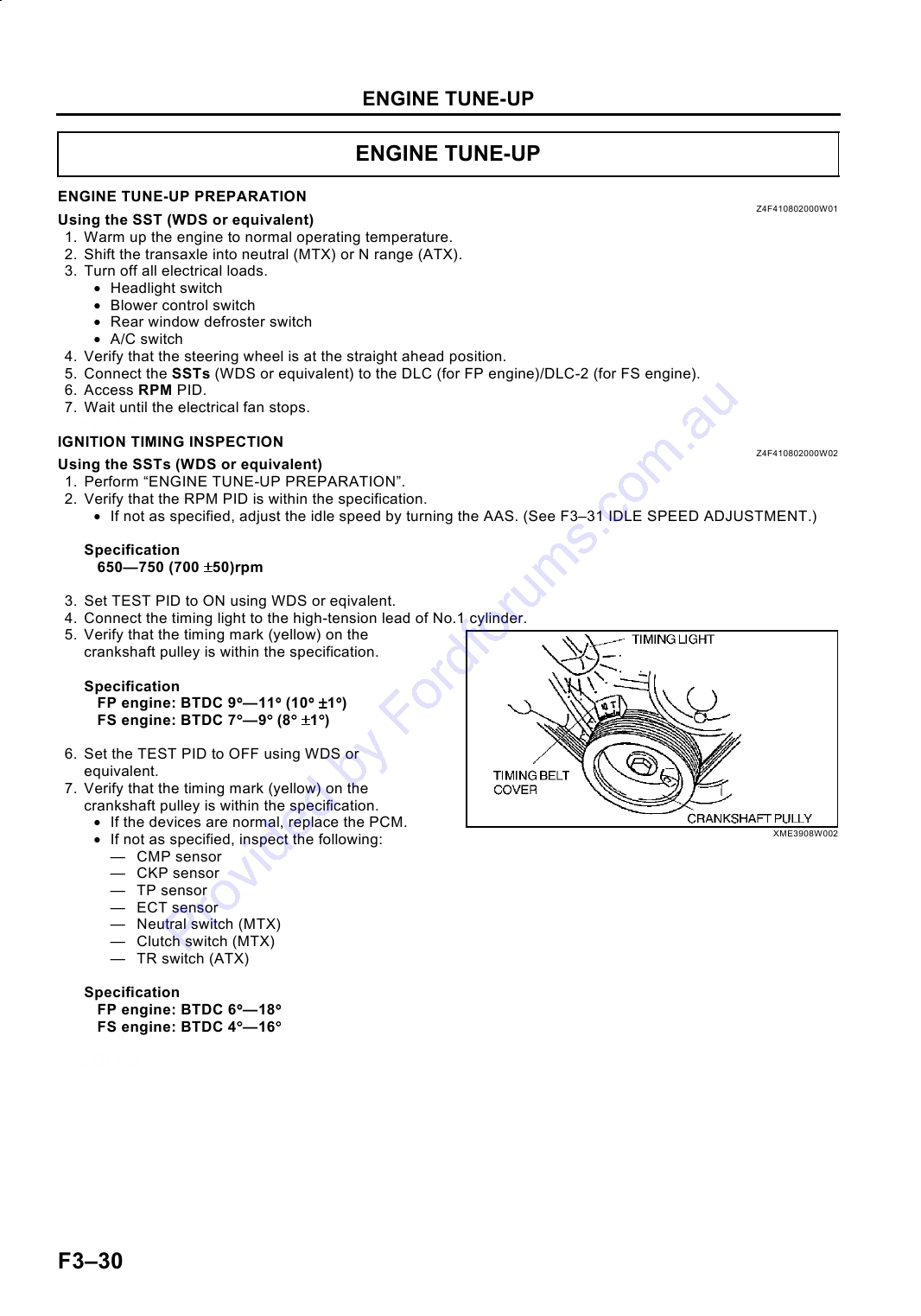
4. Connect the timing light to the high-tension lead of No.1 cylinder.
5. Verify that the timing mark (yellow) on the
crankshaft pulley is within the specification.
Specification
FP engine: BTDC 9°--11° (10° ±1°)
FS engine: BTDC 7°--9° (8° ±1°)
6. Set the TEST PID to OFF using WDS or
equivalent.
7. Verify that the timing mark (yellow) on the
crankshaft pulley is within the specification.
· If the devices are normal, replace the PCM.
· If not as specified, inspect the following:
XME3908W002
-- CMP sensor
-- CKP sensor
-- TP sensor
-- ECT sensor
-- Neutral switch (MTX)
-- Clutch switch (MTX)
-- TR switch (ATX)
Specification
FP engine: BTDC 6°--18°
FS engine: BTDC 4°--16°
End Of Sie
F330
ENGINE TUNE-UP
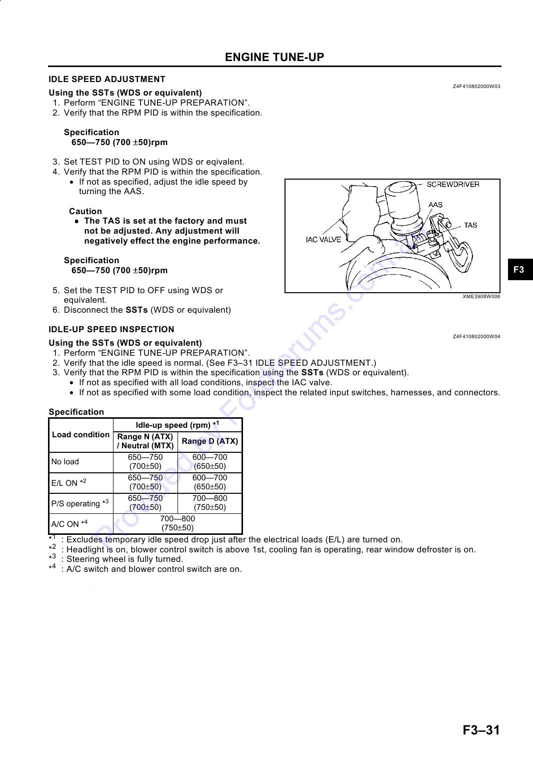
IDLE SPEED ADJUSTMENT
Z4F410802000W03
Using the SSTs (WDS or equivalent)
1. Perform "ENGINE TUNE-UP PREPARATION".
2. Verify that the RPM PID is within the specification.
Specification
650--750 (700 ±50)rpm
3. Set TEST PID to ON using WDS or eqivalent.
4. Verify that the RPM PID is within the specification.
· If not as specified, adjust the idle speed by
turning the AAS.
Caution
· The TAS is set at the factory and must
not be adjusted. Any adjustment will
negatively effect the engine performance.
Specification
650--750 (700 ±50)rpm
F3
5. Set the TEST PID to OFF using WDS or
XME3908W006
equivalent.
6. Disconnect the SSTs (WDS or equivalent)
End Of Sie
IDLE-UP SPEED INSPECTION
Z4F410802000W04
Using the SSTs (WDS or equivalent)
1. Perform "ENGINE TUNE-UP PREPARATION".
2. Verify that the idle speed is normal. (See F331 IDLE SPEED ADJUSTMENT.)
3. Verify that the RPM PID is within the specification using the SSTs (WDS or equivalent).
· If not as specified with all load conditions, inspect the IAC valve.
· If not as specified with some load condition, inspect the related input switches, harnesses, and connectors.
Specification
Idle-up speed (rpm) *1
Load condition Range N (ATX)
Range D (ATX)
/ Neutral (MTX)
650--750
600--700
No load
(700±50)
(650±50)
650--750
600--700
E/L ON *2
(700±50)
(650±50)
650--750
700--800
P/S operating *3
(700±50)
(750±50)
700--800
A/C ON *4
(750±50)
*1
: Excludes temporary idle speed drop just after the electrical loads (E/L) are turned on.
*2
: Headlight is on, blower control switch is above 1st, cooling fan is operating, rear window defroster is on.
*3
: Steering wheel is fully turned.
*4
: A/C switch and blower control switch are on.
End Of Sie
F331
INTAKE-AIR SYSTEM
INTAKE-AIR SYSTEM
VACUUM HOSE ROUTING DIAGRAM (FS)
Z4F411020030W01
Y3A4110N001
End Of Sie
IDLE AIR CONTROL (IAC) VALVE INSPECTION (FS)
Z4F411020661W01
Resistance Inspection
Note
· Perform the following test only as directed.
1. Carry out the "Idle Air Control (IAC) Inspection". (See F3241 Idle Air Control (IAC) Inspection.)
· If not as specified, perform the further inspection for the IAC valve.
2. Disconnect the battery negative cable.
3. Disconnect the IAC valve connector.
4. Measure the resistance between the IAC valve
terminals using an ohmmeter.
· If not as specified, replace the IAC valve.
· If as specified, but PID value failed, carry out
the "Circuit Open/Short Inspection".
-- If there is an open or short circuit, repair
or replace wiring harnesses.
-- If there is no open or short circuit, replace
IAC valve.
Resistance
7.7--9.3 ohms [23 °C {73 °F}]
Z3U0113W997
F332
INTAKE-AIR SYSTEM
Circuit Open/Short Inspection
1. Disconnect the PCM connector.
2. Inspect for an open or short circuit in the following wiring harnesses by probing the applicable sensor and PCM
terminals with ohmmeter leads.
Open circuit
· Power circuit (IAC valve connector terminal A and PCM connector terminal 2P)
· GND circuit (IAC valve connector terminal B and PCM connector terminal 2Q)
Short circuit
· Power circuit (IAC valve connector terminal A and PCM connector terminal 2P to GND)
· GND circuit (IAC valve connector terminal B and PCM connector terminal 2Q to GND)
3. Reconnect the IAC valve connector.
4. Reconnect the battery negative cable.
End Of Sie
VARIABLE INERTIA CHARGING SYSTEM (VICS) SOLENOID VALVE INSPECTION (FS)
Z4F411018740W01
Airflow Inspection
Note
· Perform the following inspection only when directed.
F3
1. Carry out the "VICS Operation Inspection". (See F3242 VICS Operation Inspection.)
· If not as specified, perform the further inspection for the VICS solenoid valve.
2. Disconnect the negative battery cable.
3. Remove the VICS solenoid valve.
4. Inspect for airflow between each port under the
following condition.
· If not as specified, replace the VICS solenoid
valve.
· If as specified, inspect the vacuum hose for
improper routing, kinks, or leakage.
-- If not as specified, inspect the vacuum
hose for improper routing, perform "VICS
solenoid valve circuit open/short
inspection".
Y3E4112W099
Y3E4110W002
F333
INTAKE-AIR SYSTEM
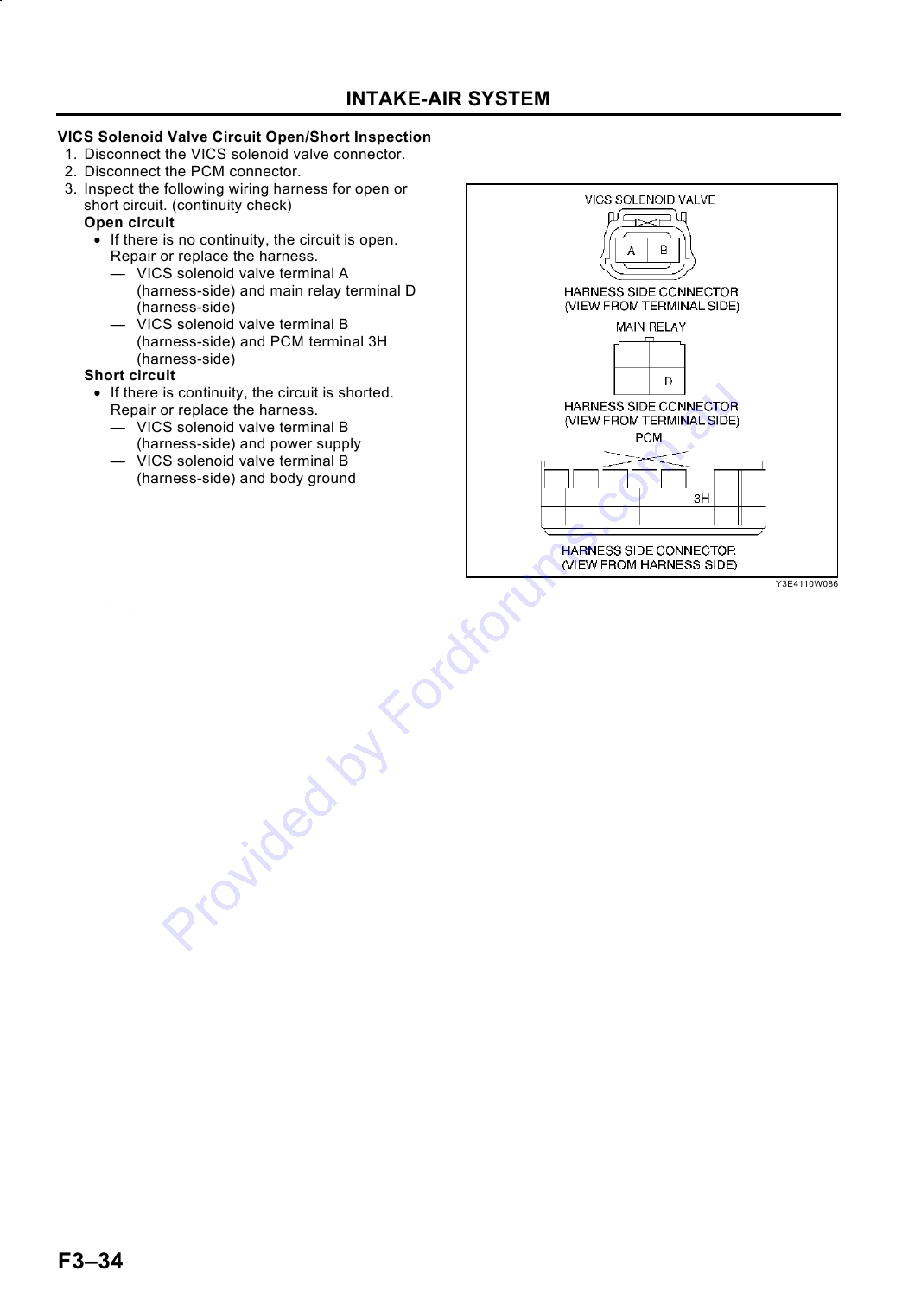
VICS Solenoid Valve Circuit Open/Short Inspection
1. Disconnect the VICS solenoid valve connector.
2. Disconnect the PCM connector.
3. Inspect the following wiring harness for open or
short circuit. (continuity check)
Open circuit
· If there is no continuity, the circuit is open.
Repair or replace the harness.
-- VICS solenoid valve terminal A
(harness-side) and main relay terminal D
(harness-side)
-- VICS solenoid valve terminal B
(harness-side) and PCM terminal 3H
(harness-side)
Short circuit
· If there is continuity, the circuit is shorted.
Repair or replace the harness.
-- VICS solenoid valve terminal B
(harness-side) and power supply
-- VICS solenoid valve terminal B
(harness-side) and body ground
Y3E4110W086
End Of Sie
F334
FUEL SYSTEM
FUEL SYSTEM
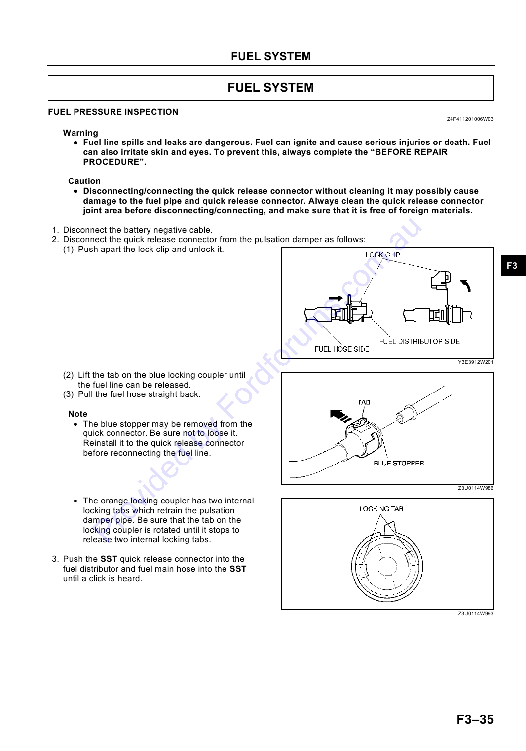
FUEL PRESSURE INSPECTION
Z4F411201006W03
Warning
· Fuel line spills and leaks are dangerous. Fuel can ignite and cause serious injuries or death. Fuel
can also irritate skin and eyes. To prevent this, always complete the "BEFORE REPAIR
PROCEDURE".
Caution
· Disconnecting/connecting the quick release connector without cleaning it may possibly cause
damage to the fuel pipe and quick release connector. Always clean the quick release connector
joint area before disconnecting/connecting, and make sure that it is free of foreign materials.
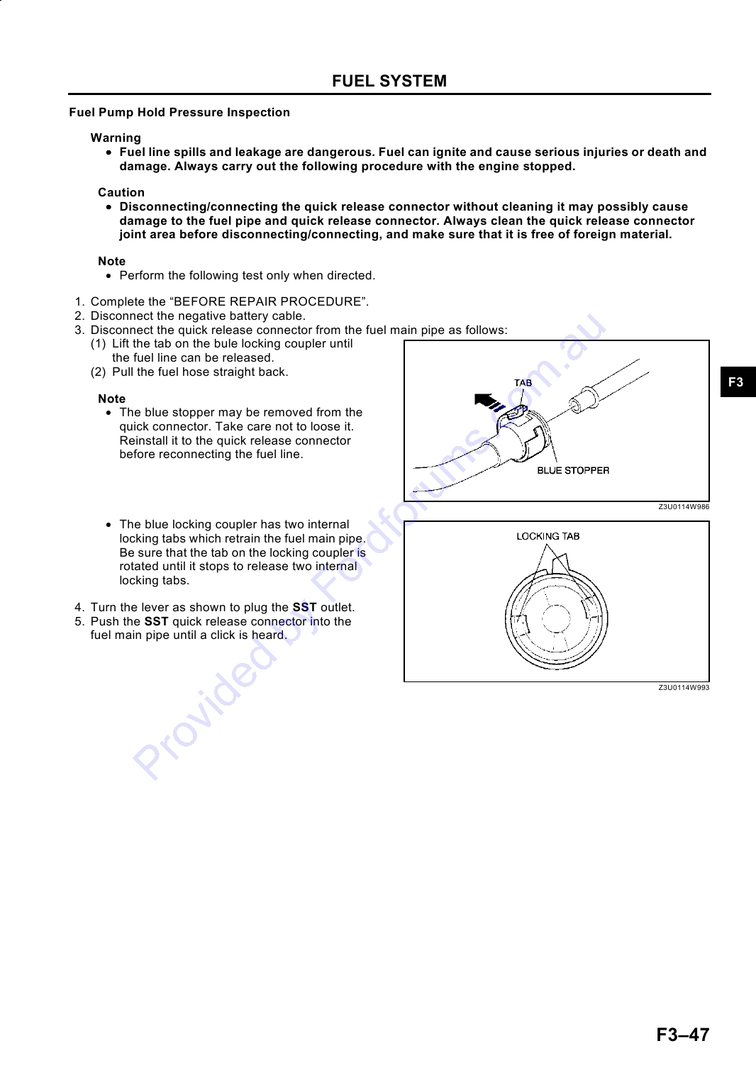
1. Disconnect the battery negative cable.
2. Disconnect the quick release connector from the pulsation damper as follows:
(1) Push apart the lock clip and unlock it.
F3
Y3E3912W201
(2) Lift the tab on the blue locking coupler until
the fuel line can be released.
(3) Pull the fuel hose straight back.
Note
· The blue stopper may be removed from the
quick connector. Be sure not to loose it.
Reinstall it to the quick release connector
before reconnecting the fuel line.
Z3U0114W986
· The orange locking coupler has two internal
locking tabs which retrain the pulsation
damper pipe. Be sure that the tab on the
locking coupler is rotated until it stops to
release two internal locking tabs.
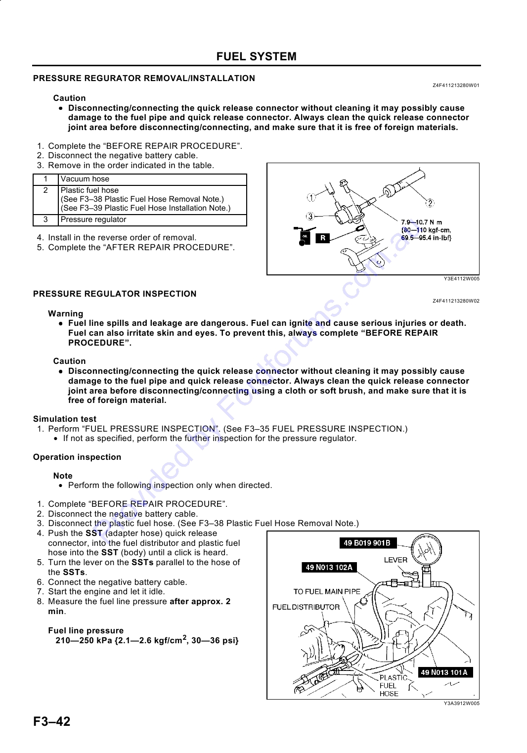
3. Push the SST quick release connector into the
fuel distributor and fuel main hose into the SST
until a click is heard.
Z3U0114W993
F335
FUEL SYSTEM
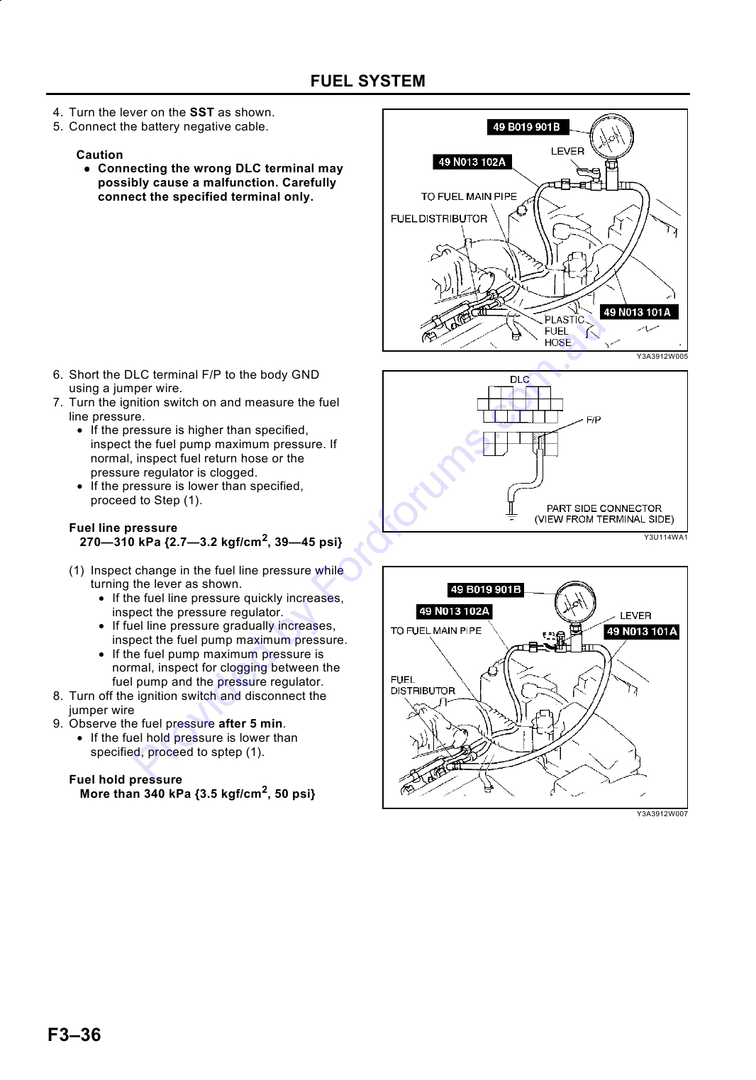
4. Turn the lever on the SST as shown.
5. Connect the battery negative cable.
Caution
· Connecting the wrong DLC terminal may
possibly cause a malfunction. Carefully
connect the specified terminal only.
Y3A3912W005
6. Short the DLC terminal F/P to the body GND
using a jumper wire.
7. Turn the ignition switch on and measure the fuel
line pressure.
· If the pressure is higher than specified,
inspect the fuel pump maximum pressure. If
normal, inspect fuel return hose or the
pressure regulator is clogged.
· If the pressure is lower than specified,
proceed to Step (1).
Fuel line pressure
270--310 kPa {2.7--3.2 kgf/cm2, 39--45 psi}
Y3U114WA1
(1) Inspect change in the fuel line pressure while
turning the lever as shown.
· If the fuel line pressure quickly increases,
inspect the pressure regulator.
· If fuel line pressure gradually increases,
inspect the fuel pump maximum pressure.
· If the fuel pump maximum pressure is
normal, inspect for clogging between the
fuel pump and the pressure regulator.
8. Turn off the ignition switch and disconnect the
jumper wire
9. Observe the fuel pressure after 5 min.
· If the fuel hold pressure is lower than
specified, proceed to sptep (1).
Fuel hold pressure
More than 340 kPa {3.5 kgf/cm2, 50 psi}
Y3A3912W007
F336
FUEL SYSTEM
(1) Inspect changes in the fule line pressure
while turning the lever as shown.
· If the fuel line pressure holds, replace the
pressure regulator. (See F337 FUEL
INJECTOR REMOVAL/INSTALLATION.)
· If the fuel line pressure does not hold,
inspect the fuel leaks from the fuel line
and the fuel injector.
10. Disconnect the SST.
Y3A3912W007
Note
· A checker is integrated with the quick
F3
release connector for new plastic fuel hoses.
The checker will be released from the quick
release connector after it is completely
engaged with the fuel pipe.
11. Inspect the plastic fuel hose and fuel pipe sealing
surface for damage and deformation, and replace
as necessary.
· If the quick release connector O-ring is
damaged or has slipped, replace the plastic
fuel hose.
Y3A4012W003
12. Reconnect the fuel main hose to the fuel
distributor until a click is heard.
13. Pull the quick release connector by hand and verify that it is installed securely.
14. Attach the lock clip to the quick release connector
in the direction of the fuel distributor and lock it,
as shown in the figure.
Y3E3912W202
End Of Sie
FUEL INJECTOR REMOVAL/INSTALLATION
Z4F411213250W01
Caution
· Disconnecting/connecting the quick release connector without cleaning it may possibly cause
damage to the fuel pipe and quick release connector. Always clean the quick release connector
joint area before disconnecting/connecting, and make sure that it is free of foreign material.
1.
Complete the "BEFORE REPAIR PROCEDURE".
2.
Disconnect the battery negative cable.
3.
Remove the accelerator cable bracket.
4.
Disconnect the fuel injector connectors and remove the harness from the fuel distributor.
F337
FUEL SYSTEM
5. Remove in the order indicated in the table.
1
Plastic fuel hose
(See F338 Plastic Fuel Hose Removal Note.)
(See F339 Plastic Fuel Hose Installation Note.)
2
Vacuum hose
3
Fuel distributor
4
Fuel distributor insulator
5
Fuel injector insulator
6
Fuel injector
(See F339 Fuel Injector Installation Note.)
7
Grommet
8
Pulsation damper
6. Install in the reverse order of removal.
7. Complete the "AFTER REPAIR PROCEDURE".
Y3A4110W001
Plastic Fuel Hose Removal Note
Caution
· The quick release connector may be damaged when the tab is turned overly. Do not turn the tab
over the stopper.
1. Disconnect the quick release connector from the pulsation damper as follows:
(1) Push apart the lock clip and unlock it.
Y3E3912W201
(2) Lift the tab on the blue locking coupler until
the fuel line can be released.
(3) Pull the fuel hose straight back.
Note
· The blue stopper may be removed from the
quick connector. Take care not to loose it.
Reinstall it to the quick release connector
before reconnecting the fuel line.
Z3U0114W986
F338
FUEL SYSTEM
· The orange locking coupler has two internal
locking tabs which retrain the pulsation
damper pipe. Be sure that the tab on the
locking coupler is rotated until it stops to
release two internal locking tabs.
2. Cover the disconnected quick release connector
and pulsation damper with vinyl sheet or the like
to prevent it from being scratched or
contaminated with foreign materials.
Z3U0114W993
Plastic Fuel Hose Installation Note
1. Inspect the plastic fuel hose and pulsation damper sealing surface for damage and deformation, and replace as
necessary.
· If the quick release connector O-ring is damaged or has slipped, replace the plastic fuel hose.
2. Apply a small amount of clean engine oil to the sealing surface of the pulsation damper.
3. Push the quick release connector straight into the pulsation damper until a click is heard.
4. Lightly pull and push the quick release connector a few times by hand and verify that it can move 2.0--3.0 mm
F3
{0.08--0.11 in} and it is connected securely.
· If quick release connector does not move at all, verify that O-ring is not damaged and slipped, and
reconnect the quick release connector.
5. Attach the lock clip to the quick release connector
in the direction of the fuel distributor and lock it,
as shown in the figure.
Y3E3912W202
Fuel Injector Installation Note
1. Install each fuel injector as indicated in the table.
Cylinder number
Fuel injector body color
No.1, No.2 cylinder
Green
No.3, No.4 cylinder
Purple
2. Use new fuel injector O-rings.
3. Apply a small amount of engine oil to the O-rings and install them into the fuel distributor.
4. Verify that the O-rings and the fuel injector sealing surfaces are free of foreign material. Clean with gasoline if
necessary.
5. Align the fuel injector notch with the fuel
distributor and install the fuel injectors in the fuel
distributor with light twisting motion so that the O-
rings will not be folded.
X3U114WC6
End Of Sie
F339
FUEL SYSTEM
FUEL INJECTOR INSPECTION (FS)
Z4F411213250W02
Simulation Test
1. Carry out the "Fuel Injector Operation Inspection". (See F3245 Fuel Injector Operation Inspection.)
· If not as specified, perform the further inspection for the fuel injectors.
Resistance Inspection
Note
· Perform the following test only when directed.
1.
Turn the ignition switch off.
2.
Disconnect the battery negative cable.
3.
Disconnect the fuel injector connectors.
4.
Measure the resistance of the fuel injector using
an ohmmeter.
· If not as specified, replace the fuel injector.
(See F337 FUEL INJECTOR REMOVAL/
INSTALLATION.)
· If as specified but "Simulation Test" is failed,
carry out the "Circuit Open/Short Inspection".
Resistance
14.2--14.8 ohms [20 °C {68 °F}]
Y3U114WA9
Circuit open/short inspection
1. Disconnect the PCM connector.
2. Inspect for an open or short circuit in the following
wiring harnesses by probing the fuel injectors and
PCM terminals with ohmmeter leads.
Open circuit
· GND circuit (No.1 cylinder fuel injector
connector terminal B and PCM connector
terminal 2A)
· GND circuit (No.2 cylinder fuel injector
connector terminal B and PCM connector
terminal 2D)
· GND circuit (No.3 cylinder fuel injector
connector terminal B and PCM connector
terminal 2G)
· GND circuit (No.4 cylinder fuel injector
connector terminal B and PCM connector
terminal 2G)
· Power circuit (No.1 cylinder fuel injector
connector terminal A and main relay
Y3A4112W001
connector terminal D through common
connector)
· Power circuit (No.2 cylinder fuel injector connector terminal A and main relay connector terminal D through
common connector)
· Power circuit (No.3 cylinder fuel injector connector terminal A and main relay connector terminal D through
common connector)
· Power circuit (No.4 cylinder fuel injector connector terminal A and main relay connector terminal D through
common connector)
Short circuit
· No.1 cylinder fuel injector connector terminal B and PCM connector terminal 2A to GND
· No.2 cylinder fuel injector connector terminal B and PCM connector terminal 2D to GND
· No.3 cylinder fuel injector connector terminal B and PCM connector terminal 2G to GND
· No.4 cylinder fuel injector connector terminal B and PCM connector terminal 2J to GND
3. Repair or replace faulty areas.
4. Reconnect the fuel injector connectors.
5. Reconnect the battery negative cable.
F340
FUEL SYSTEM
Volume Test
Warning
· Fuel line spills and leakage are dangerous. Fuel can ignite and cause serious injuries or death and
damage. Always carry out the following procedure with the engine stopped.
Note
· Perform the following test only when directed.
· If you have an after market fuel injector tester or SST (49 L018 901), perform this inspection.
· If there is no an after market fuel injector tester available, perform "Simulation Test", "Resistance
Inspection", and "Fuel Leakage Inspection" to verify whether the fuel injector is okay or not.
1. Complete the "BEFORE REPAIR PROCEDURE".
2. Disconnect the battery negative cable.
Using the SST
1. Remove the fuel injectors together with the fuel distributor with connected to fuel hose. (See F337 FUEL
INJECTOR REMOVAL/INSTALLATION.)
2. Fasten the fuel injectors firmly to the fuel distributor with wires.
3. Connect the fuel injector to the SST or the fuel
F3
injector tester as shown in the figure.
4. Connect the battery negative cable.
Caution
· Connecting the wrong DLC terminal may
possibly cause a malfunction. Carefully
connect the specified terminal only.
X3U114WJ4
5. Short the DLC terminal F/P to body GND using a
jumper wire.
6. Turn the ignition switch to ON position.
7. Measure the injection volume of each fuel injector
using a graduated container.
· If not as specified, replace the fuel injector.
Injection volume
68--75 ml {68--75 cc, 2.30--2.53 fl oz}/15 s
8. Turn the ignition switch to LOCK position.
9. Disconnect the battery negative cable.
Y3U114WA7
10. Disconnect the SST or the fuel injector tester from
the fuel injector.
11. Disconnect the jumper wire.
12. Complete the "AFTER REPAIR PROCEDURE".
Using a Fuel Injector Tester
1. Remove the fuel injectors. (See F337 FUEL INJECTOR REMOVAL/INSTALLATION.)
2. Connect the fuel injector to a fuel injector tester.
3. Measure the injection volume of each fuel injector.
· If not as specified, replace the fuel injector.
Injection volume
68--75 ml {68--75 cc, 2.3--2.5 fl oz}/15 s
4. Complete the "AFTER REPAIR PROCEDURE".
End Of Sie
F341
FUEL SYSTEM
PRESSURE REGURATOR REMOVAL/INSTALLATION
Z4F411213280W01
Caution
· Disconnecting/connecting the quick release connector without cleaning it may possibly cause
damage to the fuel pipe and quick release connector. Always clean the quick release connector
joint area before disconnecting/connecting, and make sure that it is free of foreign materials.
1. Complete the "BEFORE REPAIR PROCEDURE".
2. Disconnect the negative battery cable.
3. Remove in the order indicated in the table.
.
1
Vacuum hose
2
Plastic fuel hose
(See F338 Plastic Fuel Hose Removal Note.)
(See F339 Plastic Fuel Hose Installation Note.)
3
Pressure regulator
4. Install in the reverse order of removal.
5. Complete the "AFTER REPAIR PROCEDURE".
Y3E4112W005
End Of Sie REGULATOR INSPECTION
PRESSURE
Z4F411213280W02
Warning
· Fuel line spills and leakage are dangerous. Fuel can ignite and cause serious injuries or death.
Fuel can also irritate skin and eyes. To prevent this, always complete "BEFORE REPAIR
PROCEDURE".
Caution
· Disconnecting/connecting the quick release connector without cleaning it may possibly cause
damage to the fuel pipe and quick release connector. Always clean the quick release connector
joint area before disconnecting/connecting using a cloth or soft brush, and make sure that it is
free of foreign material.
Simulation test
1. Perform "FUEL PRESSURE INSPECTION". (See F335 FUEL PRESSURE INSPECTION.)
· If not as specified, perform the further inspection for the pressure regulator.
Operation inspection
Note
· Perform the following inspection only when directed.
1.
Complete "BEFORE REPAIR PROCEDURE".
2.
Disconnect the negative battery cable.
3.
Disconnect the plastic fuel hose. (See F338 Plastic Fuel Hose Removal Note.)
4.
Push the SST (adapter hose) quick release
connector, into the fuel distributor and plastic fuel
hose into the SST (body) until a click is heard.
5.
Turn the lever on the SSTs parallel to the hose of
the SSTs.
6.
Connect the negative battery cable.
7.
Start the engine and let it idle.
8.
Measure the fuel line pressure after approx. 2
min.
Fuel line pressure
210--250 kPa {2.1--2.6 kgf/cm2, 30--36 psi}
Y3A3912W005
F342
FUEL SYSTEM
9. Disconnect the vacuum hose from the pressure
regulator and measure the fuel line pressure.
· If not as specified, replace the pressure
regulator after inspecting the following:
-- Fuel pump maximum pressure
-- Fuel pump hold pressure
-- Fuel filter (low pressure, high pressure)
for clogging
-- Fuel injector for leakage
-- Fuel pump relay
-- Fuel line for improper routing, clogging,
kinks, or leakage
Y3E4112W007
Fuel line pressure
270--310 kPa {2.7--3.2 kgf/cm2, 39--45 psi}
10.
Turn the ignition switch to OFF.
11.
Disconnect the SSTs.
12.
Connect the plastic fuel hose. (See F339 Plastic Fuel Hose Installation Note.)
13.
Complete "AFTER REPAIR PROCEDURE".
F3
End Of Sie
PRC SOLENOID VALVE INSPECTION (FS)
Z4F411218740W01
Airflow inspection
Note
· Perform the following test only when directed.
1. Disconnect the negative battery cable.
2. Remove the PRC solenoid valve.
3. Inspect airflow between the ports under the
following conditions.
· If not as specified, replace the PRC solenoid
valve.
· If as specified but the "Simulation Test" is
failed, inspect the following:
Y3E4112W099
Y3E4112W008
F343
FUEL SYSTEM
PRC solenoid valve circuit open/short inspection
1. Disconnect the PCM connector.
2. Inspect the following wiring harness for open or
short. (continuity check)
Open circuit
· If there is no continuity, the circuit is open.
Repair or replace the harness.
-- Power circuit (PRC solenoid valve
terminal A and main relay terminal D)
-- GND circuit (PRC solenoid valve terminal
B and PCM terminal 2N)
Short circuit
· If there is continuity, the circuit is shorted.
Repair or replace the harness.
-- PRC solenoid valve terminal B
(harness-side) and power supply
-- PRC solenoid valve terminal B
(harness-side) and body ground
Y3E4112W081
End Of Sie UNIT INSPECTION
FUEL PUMP
Z4F411213350W01
Continuity Inspection
Note
· Perform the following test only when directed.
1.
Disconnect the negative battery cable.
2.
Remove the rear seat cushion.
3.
Remove the service hole cover.
4.
Disconnect the fuel pump unit connector.
5.
Inspect for continuity between fuel pump unit
connector terminals B and D.
· If there is no continuity, replace the fuel pump
body.
· If there is continuity, carry out the "Circuit
Open/Short Inspection".
Y3U114WA6
Circuit Open/Short Inspection
1. Disconnect the fuel pump relay connector and the fuel pump relay connector.
2. Inspect for an open or short circuit in the following
wiring harnesses by probing the fuel pump unit
and fuel pump relay terminals with ohmmeter
leads.
Open circuit
· GND circuit (Fuel pump unit connector
terminal D and body GND)
· Power circuit (Fuel pump relay connector
terminal E and fuel pump unit connector
terminal B through common connector)
Short circuit
· Fuel pump relay connector terminal E and
X3U114WB5
fuel pump unit connector terminal B through
common connector to GND
3. Repair or replace faulty areas.
4. Reconnect the fuel pump unit connector.
5. Install the service hole cover.
6. Install the rear seat cushion.
7. Reconnect the negative battery cable.
F344
FUEL SYSTEM
Fuel Pump Maximum Pressure Inspection
Warning
· Fuel line spills and leakage are dangerous. Fuel can ignite and cause serious injuries or death and
damage. Always carry out the following procedure with the engine stopped.
Caution
· Disconnecting/connecting the quick release connector without cleaning it may possibly cause
damage to the fuel pipe and quick release connector. Always clean the quick release connector
joint area before disconnecting/connecting, and make sure that it is free of foreign material.
Note
· Perform the following test only when directed.
1. Complete the "BEFORE REPAIR PROCEDURE".
2. Disconnect the negative battery cable.
3. Disconnect the quick release connector from the fuel main pipe as follows:
(1) Lift the tab on the bule locking coupler until
the fuel line can be released.
(2) Pull the fuel hose straight back.
F3
Note
· The blue stopper may be removed from the
quick connector. Take care not to loose it.
Reinstall it to the quick release connector
before reconnecting the fuel line.
Z3U0114W986
· The blue locking coupler has two internal
locking tabs which retrain the fuel main pipe.
Be sure that the tab on the locking coupler is
rotated until it stops to release two internal
locking tabs.
4. Turn the lever as shown to plug the SST outlet.
5. Push the SST quick release connector into the
fuel main pipe until a click is heard.
Z3U0114W993
F345
FUEL SYSTEM
6. Set the fuel hose into a container to avoid fuel
spills.
7. Connect the negative battery cable.
Caution
· Connecting the wrong DLC terminal may
possibly cause a malfunction. Carefully
connect the specified terminal only.
Y3A3912W001
8. Short the DLC terminal F/P to the body GND
using a jumper wire.
9. Turn the ignition switch to ON position to operate
the fuel pump body.
10. Measure the fuel pump maximum pressure.
· If not as specified, inspect the following:
-- Fuel pump relay
-- Fuel filters (low-pressure, high-pressure)
for clogging
-- Fuel line for clogging or leakage
Fuel pump maximum pressure
450--630 kPa {4.5--6.5 kgf/cm2, 64--92 psi}
Y3U114WA7
11. Turn the ignition switch off and disconnect the jumper wire.
12. Disconnect the SST.
13. Inspect the plastic fuel hose and fuel pipe sealing surface for damage and deformation.
· If the quick release connector O-ring is damaged or has slipped, replace the plastic fuel hose.
Note
· A checker tab is integrated with the quick
release connector for new plastic fuel hoses.
The checker tab will be released from the
quick release connector after it is completely
engaged with the fuel pipe.
14. Slightly apply clean engine oil to the sealing
surface of the fuel pipe.
15. Connect the plastic fuel hose to the fuel pipe until
a click is heard.
16. Lightly pull and push the quick release connector
a few times by hand and verify that it can move
Y3A4012W003
2.0--3.0 mm {0.08--0.11 in} and it is connected
securely.
· If quick release connector does not move at all, verify that the O-ring is not damaged and slipped, and
reconnect the quick release connector.
17. Complete the "AFTER REPAIR PROCEDURE".
F346
FUEL SYSTEM
Fuel Pump Hold Pressure Inspection
Warning
· Fuel line spills and leakage are dangerous. Fuel can ignite and cause serious injuries or death and
damage. Always carry out the following procedure with the engine stopped.
Caution
· Disconnecting/connecting the quick release connector without cleaning it may possibly cause
damage to the fuel pipe and quick release connector. Always clean the quick release connector
joint area before disconnecting/connecting, and make sure that it is free of foreign material.
Note
· Perform the following test only when directed.
1. Complete the "BEFORE REPAIR PROCEDURE".
2. Disconnect the negative battery cable.
3. Disconnect the quick release connector from the fuel main pipe as follows:
(1) Lift the tab on the bule locking coupler until
the fuel line can be released.
(2) Pull the fuel hose straight back.
F3
Note
· The blue stopper may be removed from the
quick connector. Take care not to loose it.
Reinstall it to the quick release connector
before reconnecting the fuel line.
Z3U0114W986
· The blue locking coupler has two internal
locking tabs which retrain the fuel main pipe.
Be sure that the tab on the locking coupler is
rotated until it stops to release two internal
locking tabs.
4. Turn the lever as shown to plug the SST outlet.
5. Push the SST quick release connector into the
fuel main pipe until a click is heard.
Z3U0114W993
F347
FUEL SYSTEM
6. Set the fuel hose into a container to avoid fuel
spills.
7. Connect the negative battery cable.
Caution
· Connecting the wrong DLC terminal may
possibly cause a malfunction. Carefully
connect the specified terminal only.
Y3A3912W001
8. Short the DLC terminal F/P to the body GND
using a jumper wire.
9. Turn the ignition switch to ON position for 10
seconds to operate the fuel pump body.
10. Turn the ignition switch off.
11. Measure the fuel pump hold pressure after 5
minutes.
· If not as specified, carry out the "PRESSURE
REGULATOR INSPECTION", "FUEL
INJECTOR INSPECTION". (See F342
PRESSURE REGULATOR INSPECTION.)
(See F340 FUEL INJECTOR INSPECTION
(FS).) Verify that there is no fuel leakage from
Y3U114WA7
the quick release connector joint areas.
· If all items above are okay, replace the fuel
pump body.
Fuel pump hold pressure
More than 340 kPa {3.5 kgf/cm2, 50 psi}
12. Disconnect the jumper wire.
13. Disconnect the SST.
14. Inspect the plastic fuel hose and fuel pipe sealing surface for damage and deformation.
· If the quick release connector O-ring is damaged or has slipped, replace the plastic fuel hose.
Note
· A checker tab is integrated with the quick
release connector for new plastic fuel hoses.
The checker tab will be released from the
quick release connector after it is completely
engaged with the fuel pipe.
15. Slightly apply clean engine oil to the sealing
surface of the fuel pipe.
16. Connect the plastic fuel hose to the fuel pipe until
a click is heard.
17. Lightly pull and push the quick release connector
a few times by hand and verify that it can move
2.0--3.0 mm {0.08--0.11 in} and it is connected
Y3A4012W003
securely.
· If quick release connector does not move at all, verify that the O-ring is not damaged and slipped, and
reconnect the quick release connector.
18. Complete the "AFTER REPAIR PROCEDURE".
F348
EXHAUST SYSTEM
End Of Sie
EXHAUST SYSTEM
EXHAUST SYSTEM REMOVAL/INSTALLATION
Z4F411440000W01
FP
Warning
· Hot engines and exhaust systems can cause severe burns. Turn off the engine and wait until it and
the exhaust system are cool before removing the exhaust system.
1.
Disconnect the negative battery cable.
2.
Remove the air cleaner and air hose.
3.
Remove in the order indicated in the table.
4.
Install in the reverse order of removal.
F3
Y3A4114W001
.
1
Main silencer
6
Exhaust manifold insulator
2
Pre-silencer
7
EGR pipe
3
TWC
8
Exhaust manifold
4
Front pipe
9
Exhaust manifold gasket
(See F350 Exhaust manifold gasket installation
5
HO2S (front)
note)
F349
EXHAUST SYSTEM
Exhaust manifold gasket installation note
1. When installing the exhaust manifold gasket,
make sure that the bead side of the gasket is
facing the exhaust manifold side.
XME3914W003
FS
Warning
· Hot engines and exhaust systems can cause severe burns. Turn off the engine and wait until it and
the exhaust system are cool before removing the exhaust system.
1.
Disconnect the negative battery cable.
2.
Remove the air cleaner and air hose.
3.
Remove in the order indicated in the table.
4.
Install in the reverse order of removal.
Y3E4114N001
.
1
Main silencer
9
WU-TWC gasket
(See F351 WU-TWC gasket installation note)
2
Pre-silencer
10
Exhaust manifold insulator
3
TWC
11
Exhaust manifold
4
Insulator
12
Exhaust manifold gasket
5
Front pipe
(See F350 Exhaust manifold gasket installation
6
HO2S (rear)
note)
7
EGR pipe
13
HO2S (front)
8
WU-TWC
F350
EXHAUST SYSTEM
Exhaust manifold gasket installation note
1. When installing the exhaust manifold gasket,
make sure that the bead side of the gasket is
facing the exhaust manifold side.
XME3914W003
WU-TWC gasket installation note
1. Install a new gasket with spot on the engine side.
F3
Y3E4114W005
End Of Sie
F351
EMISSION SYSTEM
EMISSION SYSTEM
CHARCOAL CANISTER INSPECTION (FS)
Z4F411613970W02
1.
Remove the air hose.
2.
Remove the charcoal canister.
3.
Plug port at the atmosphere side into port at the purge solenoid valve side.
4.
Apply pressure of 20.0 kPa {150 mmHg, 5.91 inHg} to the fuel tank side port and verify that there is no air
leakage.
· If there is air leakage, replace the charcoal
canister.
YPE3916W003
End Of Sie
PURGE SOLENOID VALVE INSPECTION (FS)
Z4F411618740W01
Simulation Test
1. Perform "Purge Control Inspection". (See F3247 Purge Control Inspection.)
· If not as specified, perform the further inspection for the purge solenoid valve.
Airflow Inspection
Note
· Perform the following inspection only when directed.
1. Disconnect the negative battery cable.
2. Remove the purge solenoid valve.
3. Inspect for airflow between the ports under the
following condition.
· If not as specified, replace the purge solenoid
valve.
· If as specified but the "Simulation Test" is
failed, inspect the vacuum hoses for improper
routing, kinks, or leakage.
-- If not as specified, "Purge solenoid valve
circuit open/short inspection".
XME3916W007
X3U116WC1
4. Install the purge solenoid valve.
5. Connect the negative battery cable.
F352
EMISSION SYSTEM
Purge solenoid valve circuit open/short inspection
1. Disconnect the PCM connector.
2. Inspect the following wiring harness for open or
short. (continuity check)
Open circuit
· If there is no continuity, the circuit is open.
Repair or replace the harness.
-- Power circuit (Purge solenoid valve
terminal A and main relay terminal D)
-- GND circuit (Purge solenoid valve
terminal B and PCM terminal 3C)
Short circuit
· If there is continuity, the circuit is shorted.
Repair or replace the harness.
-- Purge solenoid valve terminal B
(harness-side) and power supply
-- Purge solenoid valve terminal B
(harness-side) and body ground
F3
Y3E4112W050
End Of Sie INSPECTION (FS)
EGR VALVE
Z4F411620300W01
Resistance Inspection
Note
· Perform the following test only when directed.
1. Disconnect the negative battery cable.
2. Inspect resistance of the EGR valve coils.
Terminals
Resistance (ohms)
C--E
C--A
Approx. 22
D--B
D--F
· If not as specified, replace the EGR valve.
· If as specified but the "Simulation Test" is
failed, inspect the following.
Y3E4116W004
F353
EMISSION SYSTEM
Circuit Open/Short Inspection
1. Disconnect the PCM connector.
2. Inspect the following wiring harness for open or
short. (continuity check)
Open circuit
· If there is no continuity, the circuit is open. Repair
or replace the harness.
-- GND circuit (EGR valve terminal E and PCM
terminal 2E)
-- GND circuit (EGR valve terminal A and PCM
terminal 2F)
-- GND circuit (EGR valve terminal B and PCM
terminal 2H)
-- GND circuit (EGR valve terminal F and PCM
terminal 2I)
-- Power circut (EGR valve terminal C/D and
main relay terminal D through common
connector)
Short circuit
· If there is continuity, the circuit is shorted. Repair
or replace the harness.
-- EGR valve terminal E (harness-side) and
body ground
-- EGR valve terminal A (harness-side) and
body ground
-- EGR valve terminal B (harness-side) and
Y3E4112W080
body ground
-- EGR valve terminal F (harness-side) and
body ground
End Of Sie
WARM UP THREE WAY CATALYTIC CONVERTER (WU-TWC) INSPECTION (FS)
Z4F411620505W02
Note
· Make sure that no HO2S DTC has been detected. If detected, this inspection cannot be used for WU-
TWC inspection.
1. Connect the WDS or equivalent and monitor PIDs as following.
· Monitor the WU-TWC using O2S11 PID for upstream HO2S and O2S12 PID for downstream HO2S.
2. Begin to monitor the appropriate PIDs.
3. Drive the vehicle for 10 min at 65--96 km/h {40--60 mph} to ensure the WU-TWC reaches operating
temperature.
4. Stop the vehicle and leave in a safe place.
5. Let the engine at idle.
6. Record PIDs for 1 min.
7. Select the appropriate PIDs and read the graph.
8. Count the number of times (inversions) that the upstream HO2S graph line actually crosses the 0.5 V line.
9. Count the number of times (inversion) that the downstream HO2S graph line actually crosses the 0.5 V line.
Note
· Do not count the number of peaks. Refer to the illustration.
10. Using the following equation, calculate the value
of ratio.
· If the ratio is 2 or more or no downstream
HO2S inversion, the WU-TWC is functioning
properly.
· If the ratio is less than 2, the WU-TWC is not
functioning properly. Replace the WU-TWC.
Equation
RATIO = Upstream HO2S inversion ÷
downstream HO2S inversion
Z3U0116W011
F354
EMISSION SYSTEM
Upstream HO2S graphline example
Y3U116WAA
Downstream HO2S graphline example 1
Equation
RATIO = 26 inversions (upstream HO2S
inversions) ÷ 7 inversions (downstream
HO2S inversions) = 3.7 (good WU-TWC)
F3
Z3U0116W008
Downstream HO2S graphline example 2
Z3U0116W009
Downstream HO2S graphline example 3
Equation
RATIO = 26 inversions (upper stream HO2S
inversions) ÷ 19 inversions (downstream
HO2S inversions) = 1.4 (deteriorated WU-
TWC)
Z3U0116W010
End Of Sie
F355
CONTROL SYSTEM
CONTROL SYSTEM
CONTROL SYSTEM COMPONENT LOCATION INDEX (FS)
Z4F414018881W05
Y3E4140N002
.
PCM
CKP sensor
1
(See F357 PCM INSPECTION (FS))
7
(See F376 CRANKSHAFT POSITION (CKP)
SENSOR INSPECTION (FS))
IAT sensor
2
(See F371 INTAKE AIR TEMPERATURE (IAT)
Knock sensor
8
SENSOR INSPECTION (FS))
(See F377 KNOCK SENSOR INSPECTION (FS))
MAF sensor
HO2S (front)
3
(See F372 MASS AIR FLOW (MAF) SENSOR
9
(See F378 HEATED OXYGEN SENSOR (HO2S)
INSPECTION (FS))
(FRONT AND REAR) INSPECTION (FS))
TP sensor
Clutch switch (MTX)
10
(See F372 THROTTLE POSITION (TP) SENSOR
(See F380 CLUTCH SWITCH INSPECTION (FS))
INSPECTION (FS))
4
Neutral switch (MTX)
(See F373 THROTTLE POSITION (TP) SENSOR
11
(See F381 NEUTRAL SWITCH INSPECTION
ADJUSTMENT (FS))
(FS))
ECT sensor
12
TR switch (ATX)
5
(See F374 ENGINE COOLANT TEMPERATURE
PSP switch
(ECT) SENSOR INSPECTION (FS))
13
(See F382 POWER STEERING PRESSURE
CMP sensor
(PSP) SWITCH INSPECTION (FS))
6
(See F375 CAMSHAFT POSITION (CMP)
14
Brake switch
SENSOR INSPECTION (FS))
15
Battery
16
DLC
F356
CONTROL SYSTEM
17
VSS (MTX)
26
Cooling fan relay
18
VSS (ATX)
27
Condenser fan relay (with A/C)
19
IAC valve
28
Purge solenoid valve
20
VICS solenoid valve
29
EGR valve
21
Fuel injector
30
A/C relay (with A/C)
22
Fuel pump relay
31
Generator
23
Ignition coil
32
Main relay
HO2S (rear)
33
DLC-2
24
(See F378 HEATED OXYGEN SENSOR (HO2S)
Barometric pressure sensor
(FRONT AND REAR) INSPECTION (FS))
34
(See F377 BAROMETRIC PRESSURE SENSOR
25
PRC solenoid valve
INSPECTION (FS))
End Of Sie
PCM INSPECTION (FS)
Z4F414018880W01
Caution
· The PCM terminal voltages vary with change in measuring conditions and vehicle conditions.
Always carry out a total inspection of the input systems, output systems, and PCM to determine
the cause of trouble. Otherwise, a wrong diagnosis will be made.
F3
PCM Inspection Using the SST (WDS or equivalent)
Note
· PIDs for the following parts are not available on this model. Go to the appropriate part inspection page.
-- CMP sensor (See F375 CAMSHAFT POSITION (CMP) SENSOR INSPECTION (FS).)
-- Main relay
1. Connect the WDS or euivalent to the DLC-2. (See F384 ON-BOARD DIAGNOSTIC TEST (FS).)
2. Turn the ignition switch on.
3. Measure the value.
· If value is not within the specification, follow the instruction in Action column.
PID/DATA MONITOR table (Reference)
Monitor item
Unit/
Condition/Specification
PCM
Action
(Definition)
Condition
(Reference)
terminal
Inspect following PIDs: RPM, TP,
A/C operating: ON
ACCS (A/C relay)
ON/OFF
ECT, ACSW
2K
Ignition switch ON: OFF
Inspect A/C relay
A/C switch and fan switch ON: ON
Inspect A/C switch
4F
ACSW (A/C switch)
ON/OFF
A/C switch OFF: OFF
Ignition switch ON: 0%
Inspect following PIDs: IAT, RPM,
ALTF (Generator field
Idle: 0--100%
VPWR, B+2, ALTT V
3M
%
Generator operating → E/L ON:
coil control duty value)
Inspect generator
Duty value rise
Inspect following PIDs: IAT, RPM,
ALTT V (Generator
Ignition switch ON: 0 V
VPWR, B+2, ALTF
4T
V
output voltage)
Idle: 14--16 V
Inspect generator
Perform "On-Board Diagnostic Test"
ARPMDES (Target
rpm
Idle (No load): 650--750 rpm
(See F384 ON-BOARD
--
engine speed)
DIAGNOSTIC TEST (FS))
Below 400 m {0.25 mile} above sea
Inspect barometric pressure sensor
kPa
inHg
level: 99--103 kPa {29--30 inHg}
BARO (Barometric
(See F377 BAROMETRIC
4AE
pressure)
PRESSURE SENSOR INSPECTION
Below 400 m {0.25 mile} above sea
V
(FS))
level: 4.1--4.3 V
Brake pedal depressed: ON
BOO (Brake switch)
ON/OFF
Inspect brake switch
4B
Brake pedal released: OFF
CHRGLP (Generator
Ignition switch ON: ON
ON/OFF
Inspect generator warning light
3U
warning light)
Idle: OFF
COLP (Refrigerant
ON/OFF
--
--
4J
pressure switch)
Inspect clutch switch
Clutch pedal depressed: ON
2
ON/OFF
(See F380 CLUTCH SWITCH
4I
CPP* (Clutch switch)
Clutch pedal released: OFF
INSPECTION (FS))
F357
CONTROL SYSTEM
Monitor item
Unit/
Condition/Specification
PCM
Action
(Definition)
Condition
(Reference)
terminal
ECT 20 °C {68 °F}: 20 °C {68 °F}
Inspect ECT sensor
°C
°F
ECT 60 °C {140 °F}: 60 °C {140 °F}
ECT (Engine coolant
(See F374 ENGINE COOLANT
4P
ECT 20 °C {68 °F}: 2.9--3.1 V
temperature)
TEMPERATURE (ECT) SENSOR
V
INSPECTION (FS))
After warm up: 0.2--1.0 V
Inspect following PIDs: IAT, RPM,
ECT, MAF, TP, BARO, O2S11,
EVAPCP (Purge
Ignition switch ON: 0%
VPWR
solenoid valve duty
%
3C
Idle: 0%
Inspect purge solenoid valve
value)
(See F352 PURGE SOLENOID
VALVE INSPECTION (FS))
ECT above 113 °C {235 °F}: ON
DLC terminal TEN grounded and
Inspect following PIDs: RPM, TP,
FAN2 (Condenser fan
ON/OFF
throttle valve open: ON
ECT, ACSW, TEST
2C
control)
A/C operated: ON
Inspect condenser fan relay
Others: OFF
ECT above 97 °C {207 °F})
Inspect following PIDs: RPM, TP,
DLC terminal TEN grounded and
FAN3 (Cooling fan
ON/OFF
throttle valve open: ON
ECT, ACSW, TEST
2B
control)
A/C operated: ON
Inspect cooling fan relay
Others: OFF
Ignition switch ON: OFF
Inspect following PID: RPM
FP (Fuel pump relay)
ON/OFF
Idle: ON
2M
Inspect fuel pump relay
Cranking: ON
Inspect PRC solenoid valve
Ignition switch ON: OFF
FPRC (PRC solenoid
(See F343 PRC SOLENOID VALVE
2N
ON/OFF
Idle: OFF
valve)
INSPECTION (FS))
After hot start: ON
Inspect following PIDs: MAF, IAT,
RPM, TP, ECT, PNP, CPP, O2S11,
FUELPW1 (Fuel
Ignition switch ON: 0 msec
PSP, BOO, ACSW, VPWR
2A, 2D,
ms
injection duration)
Idle: 2.5--4.0 msec
Inspect CMP sensor
2G, 2J
(See F375 CAMSHAFT POSITION
(CMP) SENSOR INSPECTION (FS))
1GR: 1
1A, 1B,
Inspect following PIDs: SSA/SS1,
GEAR
2GR: 2
1C, 1V,
SSB/SS2, SSC/SS3, SSD/SS4, SSE/
1/2/3/4
(Gear position)
3GR: 3
1W
SS5
4GR: 4
Inspect following PIDs: ECT , MAF.
HTR11 (HO2S heater
Ignition switch ON (engine off): OFF Inspect HO2S heater
ON/OFF
3J
Others: ON ⇔ OFF
(Front))
(See F379 HO2S Heater (Front and
Rear) Resistance Inspection)
ECT above 90 °C {194 °F}: ON
Inspect following PIDs: ECT , MAF.
HTR12 (HO2S heater
HO2S (Rear) heater is
Inspect HO2S heater
3P
ON/OFF
(Rear))
malfunctioning: OFF
(See F379 HO2S Heater (Front and
Ignition switch ON: OFF
Rear) Resistance Inspection)
Inspect following PIDs: IAT, RPM,
ECT, MAF, TP, PNP, CPP, PSP,
Ignition switch ON: 20%
ACSW, TEST
Idle: 32--33%
2P, 2Q
IAC (IAC valve)
%
Idle (DLC terminal TEN grounded): Inspect IAC valve
(See F332 IDLE AIR CONTROL
approx. 40%
(IAC) VALVE INSPECTION (FS))
°C
°F
IAT 20 °C {68 °F}: 20 °C {68 °F}
Inspect IAT sensor
(See F371 INTAKE AIR
IAT (Intake air
IAT 20 °C {68 °F}: 2.2--2.5 V
4N
TEMPERATURE (IAT) SENSOR
temperature)
V
IAT 30 °C {86 °F}: 1.7--1.9 V
INSPECTION (FS))
Inspect VICS solenoid valve
Engine speed above 5,250 rpm:
(See F333 VARIABLE INERTIA
IVC
3H
ON/OFF
OFF
CHARGING SYSTEM (VICS)
(VICS solenoid valve)
Engine speed below 5,250 rpm: ON SOLENOID VALVE INSPECTION
(FS))
Perform "On-Board Diagnostic Test"
Ignition switch ON: 0 °
KNOCK1
°
(See F384 ON-BOARD
--
Idle: 0 °
(knock retard)
DIAGNOSTIC TEST (FS))
LPS*1 (Pressure
Change current value according to
A
Inspect pressure control solenoid
1K, 1L
throttle opening angle
control solenoid)
F358
CONTROL SYSTEM
Monitor item
Unit/
Condition/Specification
PCM
Action
(Definition)
Condition
(Reference)
terminal
Idle: 13--28% (MTX), 14.5--19%
Perform "On-Board Diagnostic Test"
(ATX)
LOAD
%
(See F384 ON-BOARD
--
Engine speed at 2,500 rpm: 12.5--
(Load)
DIAGNOSTIC TEST (FS))
17% (MTX), 13--17% (ATX)
Perform "On-Board Diagnostic Test"
LONGFT1
%
Idle: 5--5%
(See F384 ON-BOARD
--
(Long fuel trim)
DIAGNOSTIC TEST (FS))
Idle:1.6--2.5 g/s (MTX), 1.8--
2.4 g/s (ATX)
g/s
Inspect MAF sensor
Engine speed at 2,500 rpm: 6.2--
(See F372 MASS AIR FLOW (MAF)
4X
MAF (Intake MAF)
7.4 g/s (MTX), 6.5--7.9 g/s (ATX)
SENSOR INSPECTION (FS))
Ignition switch ON: 1.2--1.6 V
V
Idle: 1.5--2.5 V
MODE1 (Readiness
RFC exists: ON
ON/OFF
--
--
Function Code)
No RFC: OFF
Ignition switch ON: 0--1.0 V
Inspect HO2S
After warm up: 0--1.0 V
(See F378 HO2S (Front and Rear)
4W
O2S11 (HO2S (Front))
V
Acceleration: 0.5--1.0 V
F3
Voltage Inspection)
Deceleration: 0--0.5 V
Ignition switch ON: 0--1.0 V
Idle (After warm up): 0.5--1.0 V
Inspect HO2S
O2S12 (HO2S (Rear))
V
Idle (Engine cold): 0--0.5 V
(See F378 HO2S (Front and Rear)
4AA
Accelerate: 0.5--1.0 V
Voltage Inspection)
Decelerate: 0--0.5 V
P or N range: ON
PNP*1 (TR switch)
ON/OFF
Inspect TR switch
4H
Others: OFF
Inspect neutral switch
Shift position at neutral: ON
2
(See F381 NEUTRAL SWITCH
4H
ON/OFF
PNP* (Neutral switch)
Others: OFF
INSPECTION (FS))
Inspect PSP switch
Steering wheel is at straight ahead
(See F382 POWER STEERING
4C
PSP (PSP switch)
ON/OFF
position: OFF
PRESSURE (PSP) SWITCH
Steering wheel is fully turned: ON
INSPECTION (FS))
Inspect CKP sensor
(See F376 CRANKSHAFT
3Z, 3Y
RPM (Engine speed)
rpm
Idle: 650--750 rpm
POSITION (CKP) SENSOR
INSPECTION (FS))
Inspect following PIDs: ECT, TP.
SEGRP (EGR valve
Ignition switch ON: 0 step
Inspect EGR valve
2E, 2F,
(stepping motor)
step
Idle: 0 step
(See F353 EGR VALVE
2H, 2I
position)
Cranking: 0--60 steps
INSPECTION (FS))
Perform "On-Board Diagnostic Test"
SHRTFT1
%
Idle: -10--10%
(See F384 ON-BOARD
--
(Short fuel trim)
DIAGNOSTIC TEST (FS))
Inspect following PIDs: MAF, IAT,
RPM, TP, ECT, PSP, PNP, CPP,
Idle: BTDC 4--16°
SPARKADV (Ignition
ACSW, TEST
3F, 3I
BTDC
Idle (Terminal TEN grounded):
timing)
Perform Engine tune-up.
BTDC 7--9°
(See F330 IGNITION TIMING
INSPECTION)
SSA/SS1*1
Fourth gear: 100%
%
Inspect shift solenoid A
1A
Others: 0%
(Shift solenoid A)
SSB/SS2*1
First gear: 100%
%
Inspect shift solenoid B
1B
Others: 0%
(Shift solenoid B)
First gear: 100%
SSC/SS3*1
%
Second gear: 100%
Inspect shift solenoid C
1C
(Shift solenoid C)
Others: 0%
P or N position: ON
SSD/SS4*1
ON/OFF
1 range: ON
Inspect shift solenoid D
1V
(Shift solenoid D)
Others: OFF
TCC operating: ON
SSE/SS5*1
ON/OFF
1 range: ON
Inspect shift solenoid E
1W
(Shift solenoid E)
Others: OFF
F359
CONTROL SYSTEM
Monitor item
Unit/
Condition/Specification
PCM
Action
(Definition)
Condition
(Reference)
terminal
TCIL (HOLD indicator
HOLD mode: ON
ON/OFF
Inspect HOLD indicator light
1J
Others: OFF
light)
HOLD switch pressed: ON
TCS (HOLD switch)
ON/OFF
Inspect HOLD switch
1R
Others: OFF
TEST (TEN terminal
Open terminal TEN: OFF
Inspect DLC TEN terminal and PCM
ON/OFF
4E
(DLC))
Short terminal TEN: ON
connector terminal 4E
TFT*1 (Transaxle fluid
°C
°F
indicate transaxle fluid temperature
Inspect TFT sensor
1Q
temperature)
TFT 20 °C {68 °F}: 3.2--3.4 V
TFTV*1 (TFT sensor
V
Inspect TFT sensor
1Q
TFT 130 °C {266 °F}: 1.7--1.8 V
signal voltage)
Inspect TP sensor
TP (TP sensor signal
CTP: 0.1--1.1 V
V
(See F372 THROTTLE POSITION
4V
voltage)
WOT: 2.8--4.5 V
(TP) SENSOR INSPECTION (FS))
Inspect TP sensor
CTP: 0%
TPOD*1 (TP)
%
(See F372 THROTTLE POSITION
4V
WOT: 100%
(TP) SENSOR INSPECTION (FS))
TRD*1 (TR switch [S
S range: ON
ON/OFF
Inspect TR switch
1H
Others: OFF
range])
TRL*1 (TR switch [L
L range: ON
ON/OFF
Inspect TR switch
1E
Others: OFF
range])
TROD*1 (TR switch
D range: ON
ON/OFF
Inspect TR switch
1G
Others: OFF
[D range])
TRR*1 (TR switch
R position: ON
ON/OFF
Inspect TR switch
1D
Others: OFF
[R position])
TSS*1 (Input/turbine
Ignition switch ON: 0 rpm
rpm
Inspect input/turbine speed sensor
1N, 1O
Idle: 650--750 rpm
speed signal)
VPWR (Battery positive
Inspect main relay
V
Ignition switch ON: B+
4AF
voltage)
Inspect battery
Vehicle speed 20 km/h {12.5 mph}:
Inspect instrument cluster*2
20 km/h {12.5 mph}
VSS (Vehicle speed)
km/h
mph
3T
Vehicle speed 40 km/h {25 mph}:
Inspect VSS*1
40km/h {25 mph}
*1 : ATX only
*2 : MTX only
PCM Inspection Without Using the SST
1. Measure the voltage at each terminal.
· If any incorrect voltage is detected, inspect the related system(s), wiring harnesses and connector(s)
referring to the Action column in the terminal voltage table.
Terminal voltage table (Reference)
Voltage
Terminal
Signal
Connected to
Test condition
Action
(V)
· Inspect shift solenoid
· Inspect using the wave profile.
A
Shift solenoid A
1A*1
Shift solenoid A
(See F367 Inspection Using An
· Inspect related
control
Oscilloscope (Reference).)
harness
· Inspect shift solenoid
· Inspect using the wave profile.
B
Shift solenoid B
1B*1
Shift solenoid B
(See F367 Inspection Using An
· Inspect related
control
Oscilloscope (Reference).)
harness
· Inspect shift solenoid
· Inspect using the wave profile.
C
Shift solenoid C
1C*1
Shift solenoid C
(See F367 Inspection Using An
· Inspect related
Control
Oscilloscope (Reference).)
harness
Selector lever is
B+
· Inspect TR switch
at R position
TR switch
Ignition switch
· Inspect related
1D*1
R position
Selector lever is
(terminal C)
ON
harness
at other then R Below 1.0
position
F360
CONTROL SYSTEM
Voltage
Terminal
Signal
Connected to
Test condition
Action
(V)
Selector lever is
B+
· Inspect TR switch
at 1 range
TR switch
Ignition switch
· Inspect related
1
L range
1E*
Selector lever is
(terminal E)
ON
harness
at other then 1
Below 1.0
range
1F
--
--
--
--
--
Selector lever is
B+
· Inspect TR switch
at D range
TR switch
Ignition switch
· Inspect related
1G*1
D range
Selector lever is
(terminal G)
ON
harness
at other than D
Below 1.0
range
Selector lever is
B+
· Inspect TR switch
at 2 range
TR switch
Ignition switch
· Inspect related
1
2 range
1H*
Selector lever is
(terminal F)
ON
harness
at other then 2
Below 1.0
range
1I
--
--
--
--
--
F3
HOLD indicator
Below 1.0 · Inspect O/D OFF
light illuminates
HOLD indicator light HOLD indicator
Ignition switch
indicator light
1J*1
HOLD indicator
· Inspect related
signal
light
ON
light does not
B+
harness
illuminate
· Inspect pressure
Pressure control
Pressure control
control solenoid
1K*1
Idle
B+
· Inspect related
solenoid control (+) solenoid
harness
· Inspect pressure
· Inspect using the wave profile.
Pressure control
Pressure control
control solenoid
1L*1
(See F367 Inspection Using An
· Inspect related
solenoid control () solenoid
Oscilloscope (Reference).)
harness
· Inspect using the wave profile.
· Inspect speedometer
Vehicle speed
Speedometer (in
· Inspect related
1M*1
(See F367 Inspection Using An
output
instrument cluster)
Oscilloscope (Reference).)
harness
· Inspect input/turbine
· Inspect using the wave profile.
speed sensor
Input/turbine speed Input/turbine
1N*1
(See F367 Inspection Using An
· Inspect related
(+)
speed sensor
Oscilloscope (Reference).)
harness
· Inspect input/turbine
Input/turbine speed Input/turbine
speed sensor
1O*1
Idle
Below 1.0
· Inspect related
()
speed sensor
harness
1P
--
--
--
--
--
TFT 20 °C
· Inspect TFT sensor
3--4
Ignition switch {68 °F}
· Inspect related
1Q*1
TFT
TFT sensor
TFT 130 °C
ON
harness
0.2--0.7
{266 °F}
Below 1.0 · Inspect O/D OFF
HOLD switch
Ignition switch pushed
switch
1R*1
HOLD signal
HOLD switch
· Inspect related
ON
HOLD switch
B+
harness
released
1S
--
--
--
--
--
1T
--
--
--
--
--
1U
--
--
--
--
--
· Inspect shift solenoid
Selector lever is
at P, N position
B+
Shift solenoid D
D
1V*1
Shift solenoid D
Idle
· Inspect related
and L range
control
harness
Others
Below 1.0
Below 1.0 · Inspect shift solenoid
Idle (P position)
Shift solenoid E
E
1W*1
Shift solenoid E
· Inspect related
control
L range (1GR)
B+
harness
1V
--
--
--
--
--
F361
CONTROL SYSTEM
Voltage
Terminal
Signal
Connected to
Test condition
Action
(V)
· Inspect fuel injector
No.1
· Inspect using the wave profile.
(See F340 FUEL
INJECTOR
2A
Fuel injection (#1)
Fuel injector No.1
(See F367 Inspection Using An
INSPECTION (FS))
Oscilloscope (Reference).)
· Inspect related
harness
Ignition switch ON
B+
· Inspect cooling fan
Cooling fan
relay
2B
Cooling fan control
Cooling fan relay
Below 1.0
· Inspect related
operating
Idle
harness
Others
B+
Ignition switch ON
B+
· Inspect condenser fan
Condenser fan
Condenser fan
Condenser fan
relay
2C
Below 1.0
· Inspect related
control
relay
operating
Idle
harness
Others
B+
· Inspect fuel injector
· Inspect using the wave
No.2
(See F340 FUEL
profile.
B+
INJECTOR
2D
Fuel injection (#2)
Fuel injector No.2
(See F367 Inspection Using
INSPECTION (FS))
An Oscilloscope
· Inspect related
(Reference).)
harness
Below 1.0 · Inspect EGR valve
Ignition switch ON
(See F353 EGR
VALVE INSPECTION
EGR valve #1 coil
EGR valve
2E
control
(terminal E)
(FS))
Idle
Below 1.0
· Inspect related
harness
· Inspect EGR valve
Ignition switch ON
B+
(See F353 EGR
EGR valve #2 coil
EGR valve
VALVE INSPECTION
2F
control
(terminal A)
(FS))
Idle
B+
· Inspect related
harness
· Inspect fuel injector
No.3
· Inspect using the wave profile.
(See F340 FUEL
INJECTOR
2G
Fuel injection (#3)
Fuel injector No.3
(See F367 Inspection Using An
INSPECTION (FS))
Oscilloscope (Reference).)
· Inspect related
harness
· Inspect EGR valve
Ignition switch ON
B+
(See F353 EGR
EGR valve #3 coil
EGR valve
VALVE INSPECTION
2H
control
(terminal B)
(FS))
Idle
B+
· Inspect related
harness
Below 1.0 · Inspect EGR valve
Ignition switch ON
(See F353 EGR
EGR valve #4 coil
EGR valve
VALVE INSPECTION
2I
control
(terminal F)
(FS))
Idle
Below 1.0
· Inspect related
harness
· Inspect fuel injector
No.4
· Inspect using the wave profile.
(See F340 FUEL
INJECTOR
2J
Fuel injection (#4)
Fuel injector No.4
(See F367 Inspection Using An
INSPECTION (FS))
Oscilloscope (Reference).)
· Inspect related
harness
Below 1.0 · Inspect A/C relay
A/C operating
· Inspect related
2K
A/C
A/C relay
A/C not operating
B+
harness
2L
--
--
--
--
--
F362
CONTROL SYSTEM
Voltage
Terminal
Signal
Connected to
Test condition
Action
(V)
· Inspect fuel pump
Ignition switch ON
B+
relay
Cranking
Below 1.0
2M
Fuel pump control
Fuel pump relay
· Inspect related
Idle
Below 1.0
harness
· Inspect PRC solenoid
Ignition switch ON
B+
valve
(See F343 PRC
PRC solenoid
2N
PRC
SOLENOID VALVE
valve
After hot start
Below 1.0
INSPECTION (FS))
· Inspect related
harness
2O
--
--
--
--
--
· Inspect IAC valve
Ignition switch ON
B+
(See F332 IDLE AIR
CONTROL (IAC)
2P
IAC (+)
IAC valve
VALVE INSPECTION
Idle
B+
(FS))
· Inspect related
F3
harness
· Inspect IAC valve
(See F332 IDLE AIR
· Inspect using the wave profile.
CONTROL (IAC)
VALVE INSPECTION
2Q
IAC ()
IAC valve
(See F367 Inspection Using An
(FS))
Oscilloscope (Reference).)
· Inspect related
harness
2R
--
--
--
--
--
· Inspect related
3A
GND
GND
Under any condition
Below 1.0
harness
· Inspect related
3B
GND
GND
Under any condition
Below 1.0
harness
· Inspect purge
solenoid valve
· Inspect using the wave profile.
(See F352 PURGE
Purge solenoid
SOLENOID VALVE
3C
Purge control
(See F367 Inspection Using An
valve
INSPECTION (FS))
Oscilloscope (Reference).)
· Inspect related
harness
3D
--
--
--
--
--
3E
--
--
--
--
--
· Inspect ignition coil
· Inspect using the wave profile.
Ignition coil (No. 1,
· Inspect related
3F
IGT1
(See F367 Inspection Using An
4 cylinders)
harness
Oscilloscope (Reference).)
3G
--
--
--
--
--
· Inspect VICS solenoid
Engine speed: above 5,250 rpm
B+
valve
(See F333
VARIABLE INERTIA
CHARGING SYSTEM
VICS solenoid
3H
VICS control
(VICS) SOLENOID
valve
Engine speed: below 5,250 rpm Below 1.0
VALVE INSPECTION
(FS))
· Inspect related
harness
· Inspect ignition coil
· Inspect using the wave profile.
Ignition coil (No. 2,
· Inspect related
3I
IGT2
(See F367 Inspection Using An
3 cylinders)
harness
Oscilloscope (Reference).)
· Inspect HO2S (Front)
Ignition switch ON (engine
B+
stopped)
heater.
(See F379 HO2S
Approx. 15 seconds after engine
HO2S (Front)
HO2S (Front)
Heater (Front and
start with ECT 20--30°C {68--86 Below 1.0
3J
heater control
heater
Rear) Resistance
°F}
Inspection)
Below 1.0 · Inspect related
Others
⇔ B+
harness
F363
CONTROL SYSTEM
Voltage
Terminal
Signal
Connected to
Test condition
Action
(V)
3K
--
--
--
--
--
3L
--
--
--
--
--
· Inspect generator
· Inspect using the wave profile.
Generator field coil Generator
· Inspect related
3M
(See F367 Inspection Using An
control
(terminal D)
harness
Oscilloscope (Reference).)
3N
--
--
--
--
--
3O
--
--
--
--
--
· Inspect HO2S (Rear)
ECT above
Below 1.0
70 °C {158 °F}
(See F379 HO2S
Heater (Front and
HO2S (Rear) heater
3P
HO2S (Rear)
Idle
Rear) Resistance
control
HO2S (Rear) is
Inspection)
B+
malfunctioning
· Inspect related
harness
Because this terminal is for serial
· Inspect related
K-LINE (serial
3Q
DLC terminal KLN communication, good/no good judgment by
communication)
harness
terminal voltage is not possible.
3R
--
--
--
--
--
· Inspect immobilizer
Because this terminal is for serial
Immobilizer (serial
unit
3S
Immobilizer unit
communication, good/no good judgment by
· Inspect related
communication)
terminal voltage is not possible.
harness
· Inspect instrument
cluster
Speedometer
· Inspect related
· Inspect using the wave profile.
(MTX)
harness
3T
Vehicle speed
(See F367 Inspection Using An
· Inspect VSS
Oscilloscope (Reference).)
· Inspect related
VSS (ATX)
harness
approx. · Inspect generator
Generator warning Ignition switch ON
Generator warning
2.0
warning light
light (in instrument
3U
· Inspect related
light control
cluster)
Idle
B+
harness
· Inspect CMP sensor
(See F375
CAMSHAFT
· Inspect using the wave profile.
POSITION (CMP)
3V
SGC(+)
CMP sensor
(See F367 Inspection Using An
SENSOR
Oscilloscope (Reference).)
INSPECTION (FS))
· Inspect related
harness
· Inspect CMP sensor
(See F375
CAMSHAFT
POSITION (CMP)
3W
SGC()
CMP sensor
Idle
0V
SENSOR
INSPECTION (FS))
· Inspect related
harness
3X
--
--
--
--
--
· Inspect CKP sensor
(See F376
CRANKSHAFT
· Inspect using the wave profile.
POSITION (CKP)
3Y
NE (+)
CKP sensor
(See F367 Inspection Using An
SENSOR
Oscilloscope (Reference).)
INSPECTION (FS))
· Inspect related
harness
F364
CONTROL SYSTEM
Voltage
Terminal
Signal
Connected to
Test condition
Action
(V)
· Inspect CKP sensor
(See F376
CRANKSHAFT
POSITION (CKP)
3Z
NE ()
CKP sensor
Idle
0V
SENSOR
INSPECTION (FS))
· Inspect related
harness
· Inspect related
4A
GND
GND
Under any condition
Below 1.0
harness
· Inspect brake switch
Brake pedal depressed
B+
· Inspect related
4B
Brake
Brake switch
Brake pedal released
Below 1.0
harness
· Inspect PSP switch
Steering wheel
at straight
B+
(See F382 POWER
ahead position
STEERING
PRESSURE (PSP)
SWITCH
4C
PSP
PSP switch
Idle
F3
INSPECTION (FS))
While turning
Below 1.0 · Inspect power
steering wheel
steering system
· Inspect related
harness
4D
--
--
--
--
--
Open terminal
B+
· Inspect related
Ignition switch TEN
Diagnostic test
4E
DLC terminal TEN
harness
mode
ON
Short to ground
Below 1.0
terminal TEN
· Inspect A/C switch
A/C switch and
Below 1.0
Refrigerant
· Inspect related
fan switch on
4F
A/C on signal
Idle
pressure switch
harness
A/C switch off
B+
4G
--
--
--
--
--
· Inspect neutral switch
Shift lever is at neutral position
Below 1.0
(See F381
Neutral position
NEUTRAL SWITCH
Neutral switch
Shift lever is not at neutral
(MTX)
INSPECTION (FS))
B+
position
· Inspect related
4H
harness
Selector lever is
Below 1.0 · Inspect TR switch
Ignition switch at P or N
Load/no load signal TR switch
· Inspect related
position
(ATX)
(terminal H)
ON
harness
Others
B+
Below 1.0 · Inspect clutch switch
Clutch pedal depressed
(See F380 CLUTCH
Clutch operation
SWITCH
4I
Clutch switch
(MTX)
INSPECTION (FS))
Clutch pedal released
B+
· Inspect related
harness
4J
--
--
--
--
--
4K
--
--
--
--
--
Approx. · Inspect related
Constant voltage
TP sensor, BARO
4L
Ignition switch ON
(Vref)
sensor
5.0
harness
· Inspect knock sensor
Ignition switch ON (Use digital
type voltmeter, because
(See F377 KNOCK
measurement voltage will be
SENSOR
4M
Knocking
Knock sensor
Below 1.0
detected less than true voltage
INSPECTION (FS))
· Inspect related
when using analog type
voltmeter)
harness
F365
CONTROL SYSTEM
Voltage
Terminal
Signal
Connected to
Test condition
Action
(V)
IAT 20 °C
· Inspect IAT sensor
2.3--2.4
{68 °F}
(See F371 INTAKE
AIR TEMPERATURE
Ignition switch
4N
IAT
IAT sensor
(IAT) SENSOR
IAT 30 °C
ON
INSPECTION (FS))
1.7--1.9
{86 °F}
· Inspect related
harness
ECT sensor, IAT
sensor, BARO
· Inspect related
sensor, TP
Under any condition
Below 1.0
4O
Sensor GND
sensor, HO2S
harness
(Front, Rear), TFT
sensor
ECT 20 °C
· Inspect ECT sensor
2.9--3.1
{68 °F}
(See F374 ENGINE
COOLANT
Ignition switch
TEMPERATURE
4P
ECT
ECT sensor
ON
(ECT) SENSOR
After warm up
0.2--1.0
INSPECTION (FS))
· Inspect related
harness
4Q
--
--
--
--
--
· Inspect ABS/TCS CU
Because this terminal is for serial
· Inspect related
4R
TCS INH
ABS/TCS CU
communication, good/no good judgment by
harness
terminal voltage is not possible.
4S
--
--
--
--
--
· Inspect generator
· Inspect using the wave profile.
Generator output
Generator
· Inspect related
4T
(See F367 Inspection Using An
voltage
(terminal P)
harness
Oscilloscope (Reference).)
· Inspect ABS/TCS CU
Because this terminal is for serial
· Inspect related
4U
TCS TS
ABS/TCS CU
communication, good/no good judgment by
terminal voltage is not possible.
harness
0.1--1.1 · Inspect TP sensor
CTP
(See F372
THROTTLE
POSITION (TP)
Ignition switch
4V
Throttle position
TP sensor
SENSOR
ON
WOT
3.0--4.6
INSPECTION (FS))
· Inspect related
harness
· Inspect HO2S (Front)
(See F378 HO2S
· Inspect using the wave profile.
(Front and Rear)
4W
HO2S (Front)
HO2S (Front)
(See F367 Inspection Using An
Voltage Inspection)
Oscilloscope (Reference).)
· Inspect related
harness
0.9--2.0 · Inspect MAF sensor
Ignition switch ON
(See F372 MASS
AIR FLOW (MAF)
4X
MAF
MAF sensor
SENSOR
Idle
1.7--2.4
INSPECTION (FS))
· Inspect related
harness
4Y
--
--
--
--
--
4Z
--
--
--
--
--
Below 1.0 · Inspect HO2S (Rear)
Ignition switch ON
(See F378 HO2S
Engine cold
Approx. 0
(Front and Rear)
Catalytic converter
4AA
HO2S (Rear)
Voltage Inspection)
efficiency
Idle
0.5--0.9 · Inspect related
After warm up
harness
4AB
--
--
--
--
--
4AC
--
--
--
--
--
4AD
--
--
--
--
--
F366
CONTROL SYSTEM
Voltage
Terminal
Signal
Connected to
Test condition
Action
(V)
· Inspect EGR boost
sensor
(See F377
BAROMETRIC
Ignition switch ON (Barometric
Approx.
PRESSURE
4AE
BARO
BARO sensor
pressure at 102 kPa
4.0
SENSOR
{765 mmHg, 30 inHg})
INSPECTION (FS))
· Inspect related
harness
Below 1.0 · Inspect battery
Ignition switch OFF
· Inspect EGI fuse
· Inspect related
4AF
B+
Main relay
Ignition switch ON
B+
harness
· Inspect battery
· Inspect EGI fuse
Back-up power
Battery (positive
4AG
Under any condition
B+
· Inspect related
supply
terminal)
harness
Below 1.0 · Inspect battery
F3
Ignition switch OFF
· Inspect EGI fuse
· Inspect related
4AH
B+
Main relay
Ignition switch ON
B+
harness
*1 : ATX only
Inspection Using An Oscilloscope (Reference)
Shift solenoid A control
· PCM terminal: 1A(+)--4A(-)
· Oscilloscope setting: 5 V/DIV(Y), 5 ms/DIV(X),
DC range
· Vehicle condition: drive in the 4th gear
Z3U0140W016
Shift solenoid B cointrol signal
· PCM terminal: 1B(+)--4A(-)
· Oscilloscope setting: 5 V/DIV(Y), 5ms/DIV(X), DC
range
· Vehicle condition: Drive in D range, 1st gear
Z3U0140W016
F367
CONTROL SYSTEM
Shift solenoid C cointrol signal
· PCM terminal: 1C(+)--4A(-)
· Oscilloscope setting: 5 V/DIV(Y), 5 ms/DIV(X),
DC range
· Vehicle condition: Drive in 1st or 2nd gear
Z3U0140W016
Pressure control solenoid control signal
CTP
· PCM terminal: 1L(+)--4A(-)
· Oscilloscope setting: 2.5 V/DIV(Y), 0.8 ms/
DIV(X), DC range
· Vehicle condition: ignition key at ON (Engine
OFF) and closed throttle position
Y3A4140W001
WOT
· PCM terminal: 1L(+)--4A(-)
· Oscilloscope setting: 2.5 V/DIV(Y), 0.8 ms/
DIV(X), DC range
· Vehicle condition: ignition key at ON (Engine
OFF) and wide open throttle
Y3A4140W002
Input/turbine speed signal
· PCM terminal: 1N(+)--4A(-)
· Oscilloscope setting: 1 V/DIV(Y), 0.8 ms/DIV(X),
DC range
· Vehicle condition: idle after warm up
Y3A4140W003
F368
CONTROL SYSTEM
Fuel injection signal
· PCM terminal
-- No.1:2A(+)--3A(-)
-- No.2:2D(+)--3A(-)
-- No.3:2G(+)--3A(-)
-- No.4:2J(+)--3A(-)
· Oscilloscope setting: 2.5 V/DIV(Y), 10 ms/DIV(X),
DC range
· Vehicle condition: idle after warm up
Y3A4140W004
IAC signal
· PCM terminal: 2Q(+)--4A(-)
· Oscilloscope setting: 2.5 V/DIV(Y), 0.8 ms/
DIV(X), DC range
· Vehicle condition: idle after warm up
F3
Y3A4140W005
Purge control signal
· PCM terminal: 3C(+)--4A(-)
· Oscilloscope setting: 4 V/DIV(Y), 20 ms/DIV(X),
DC range
· Vehicle condition: idle after warm up
Z3U0140W014
IGT signal
· PCM terminal:
-- IGT1: 3F(+)--4A(-)
-- IGT2: 3I(+)--4A(-)
· Oscilloscope setting: 1 V/DIV(Y), 10 ms/DIV(X),
DC range
· Vehicle condition: idle after warm up
Y3A4140W006
F369
CONTROL SYSTEM
Generator field coil control signal
· PCM terminal: 3M(+)--4A(-)
· Oscilloscope setting: 0.2 V/DIV(Y), 2ms/DIV(X),
DC range
· Vehicle condition: idle after warm up
Z3U0140W012
Vehicle speed signal
· PCM terminal: 3T(+)--4A(-)
· Oscilloscope setting: 2 V/DIV(Y), 2.5 ms/DIV(X),
DC range
· Vehicle condition: drive the vehicle with 40 km/h
[25 mph]
Y3A4140W007
SGC signal
· PCM terminal: 3V(+)--3A(-)
· Oscilloscope setting: 1 V/DIV(Y), 20 ms/DIV(X),
AC range
· Vehicle condition: idle after warm up
Y3A4140W008
Ne signal
· PCM terminal: 3Y(+)--3A(-)
· Oscilloscope setting: 2 V/DIV(Y), 8 ms/DIV(X),
DC range
· Vehicle condition: idle after warm up
Y3A4140W009
F370
CONTROL SYSTEM
Generator output voltage signal
· PCM terminal: 4T(+)--4A(-)
· Oscilloscope setting: 2 V/DIV(Y), 5 ms/DIV(X),
DC range
· Vehicle condition: idle after warm up
Z3U0140W009
HO2S (Front) signal
· PCM terminal: 4W(+)--3A(-)
· Oscilloscope setting: 0.25 V/DIV(Y), 0.8 s/DIV(X),
DC range
· Vehicle condition: idle after warm up
F3
Y3A4140W010
End Of Sie TEMPERATURE (IAT) SENSOR INSPECTION (FS)
INTAKE AIR
Z4F414018845W01
Resistance Inspection
Note
· Perform the following test only when directed.
1. Remove the IAT sensor.
2. Measure the resistance of the IAT sensor
terminals A and B using an ohmmeter.
· If not as specified, replace the IAT sensor. If
IAT sensor is okay, but PID value is out of
specification, inspect the following:
Ambient temperature (°C {°F})
Resistance (kilohm)
10 {50}
3.1--4.4
20 {68}
2.2--2.7
30 {86}
1.4--1.9
Open circuit
· IAT signal circuit (IAT sensor connector
terminal A and PCM connector terminal 4N)
· GND circuit (IAT sensor connector terminal B
and PCM connector terminal 4O through
common connector)
Short circuit
Y3E4140W008
· IAT signal circuit (IAT sensor connector
terminal A and PCM connector terminal 4N)
3. Repair or replace faulty areas.
4. Install the IAT sensor.
End Of Sie
F371
CONTROL SYSTEM
MASS AIR FLOW (MAF) SENSOR INSPECTION (FS)
Z4F414013210W01
Note
· Perform the following test only when directed.
1. Disconnect the negative battery cable.
2. Visually inspect for the following on the MAF sensor.
· If any of the above are found, replace the MAF sensor.
· If all of the above are okay but the PID value is failed, perform "MAF sensor circuit open/short inspection".
-- Damage
-- Cracks
-- Terminal bends
-- Terminal rust
3. Connect the negative battery cable.
MAF sensor circuit open/short inspection
1. Disconnect the PCM connector.
2. Inspect the following wiring harness for open or
short. (continuity check)
Open circuit
· If there is no continuity, the circuit is open. Repair
or replace the harness.
-- MAF sensor terminal B (harness-side) and
main relay terminal 4X (harness-side)
-- MAF sensor terminal C (harness-side) and
main relay terminal D (harness-side)
-- MAF sensor terminal A (harness-side) and
PCM terminal 4A (harness-side)
Short circuit
· If there is continuity, the circuit is shorted. Repair
or replace the harness.
-- MAF sensor terminal B (harness-side) and
power supply
-- MAF sensor terminal C (harness-side) and
main relay terminal D (harness-side)
Y3E4140W009
End Of Sie
THROTTLE POSITION (TP) SENSOR INSPECTION (FS)
Z4F414018910W01
Resistance Inspection
1. Perform the following test only when directed.
· If not as specified, inspect following:
-- Throttle valve CTP
-- Accelerator cable free play
· If as specified but PID value is out of specification, inspect resistance of the TP sensor.
2. Disconnect the TP sensor connector.
3. Measure the resistance between the TP sensor
terminals A and C using an ohmmeter.
· If not as specified, adjust the TP sensor. (See
F373 THROTTLE POSITION (TP) SENSOR
ADJUSTMENT (FS).)
· If as specified, inspect the following:
Specification
4--6 kilohm
Open circuit
· Constant voltage circuit (TP sensor connector
terminal A and PCM connector terminal 4L)
· TP signal circuit (TP sensor connector
terminal B and PCM connector terminal 4V)
· GND circuit (TP sensor connector terminal C
and PCM connector terminal 4O)
Y3E4140W010
F372
CONTROL SYSTEM
Short circuit
· Constant voltage circuit (TP sensor connector terminal A and PCM connector terminal 4L)
· TP signal circuit (TP sensor connector terminal B and PCM connector terminal 4V)
4. Repair of replace faulty areas.
5. Reconnect the TP sensor connector.
End Of Sie
THROTTLE POSITION (TP) SENSOR ADJUSTMENT (FS)
Z4F414018910W02
Caution
· Adjusting the TP sensor with the TAS can adversely affect the engine. Do not adjust the TP sensor
with the TAS.
· Since the TP sensor is adjusted by the manufacturer, adjusting the TP sensor excessively can
adversely affect the engine. Do not adjust the TP sensor excessively.
1. Verify that the throttle valve is at CTP.
· If not as specified, replace the throttle body.
2. Disconnect the TP sensor connector.
3. Turn ignition switch on.
4. Measure and record the voltage of the
disconnected harness side connector terminal C
F3
using a voltmeter.
Specification
4.5--5.5 V
5. Connect the TP sensor connector.
Y3E4140W012
6. Loosen the TP sensor screws.
Y3E4140W013
F373
CONTROL SYSTEM
7. Use the WDS or equivalent ("TP" of PID/DATA
MONITOR AND RECORD function) or voltmeter
to adjust the TP sensor so that the voltage of
PCM terminal 4V is within the specification below
when the throttle valve is at the CTP.
Specification (CTP)
TP sensor terminal C
PCM terminal 4V voltage
voltage (V)
TP (WDS)
4.5--4.9
0.4--0.5
4.9--5.1
0.4--0.6
5.1--5.5
0.5--0.6
8. Tighten the TP sensor screws.
Tightening torque
1.6--2.3 N·m {16--24 kgf·cm, 14--20 in·lbf}
9. Use the WDS or equivalent ("TP" of PID/DATA
MONITOR AND RECORD function) or voltmeter
to verify the TP sensor so that the voltage of PCM
terminal 4V is within the specification below when
the throttle valve is wide open.
· If not as specified, replace the TP sensor.
Y3E4140W014
Specification (WOT)
TP sensor terminal C
PCM terminal 4V voltage
voltage (V)
TP (WDS)
4.5--4.7
3.5--4.4
4.7--4.8
3.6--4.5
4.8--4.9
3.7--4.6
4.9--5.0
3.7--4.8
5.0--5.1
3.8--4.9
5.1--5.3
4.0--5.0
5.3--5.4
4.1--5.1
5.4--5.5
4.2--5.2
End Of Sie
ENGINE COOLANT TEMPERATURE (ECT) SENSOR INSPECTION (FS)
Z4F414018840W01
Note
· Perform the following test only when directed.
ECT Sensor Resistance Inspection
1. Drain the engine coolant.
2. Remove the ECT sensor.
F374
CONTROL SYSTEM
3. Place the ECT sensor in water with a
thermometer, and heat the water gradually.
4. Measure the resistance between the ECT sensor
terminals A and B using an ohmmeter.
· If the ECT sensor is okay, but PID value is out
of specification, carry out the "Circuit Open/
Short Inspection".
· If not as specified, replace the ECT sensor.
Specification
Water temperature (°C {°F})
Resistance (kilohm)
20 {68}
2.2--2.8
80 {176}
0.29--0.40
F3
Y3E4140W015
Circuit Open/Short Inspection
1. Inspect for an open or short circuit in the following
wiring harness.
· If there is an open or short circuit, repair or
replace wiring harness.
Open circuit
· ECT signal circuit (ECT sensor connector
terminal A and PCM connector terminal 4P
through common connector)
· GND circuit (ECT sensor connector terminal
B and PCM connector terminal 4O)
Short circuit
· ECT signal circuit (ECT sensor connector
terminal A and PCM connector terminal 4P to
GND).
· GND circuit (ECT sensor connector terminal
B and PCM connector terminal 4O to GND)
2. Install the ECT sensor.
Y3E4140W087
End Of Sie POSITION (CMP) SENSOR INSPECTION (FS)
CAMSHAFT
Z4F414018200W01
Resistance Inspection
Note
· Perform the following test only when directed.
1. Disconnect the CMP sensor connector.
2. Measure the resistance between the CMP sensor
connector terminals A and B using an ohmmeter.
· If not as specified, replace the CMP sensor.
· If CMP sensor resistance is okay, but PID
value is out of specification, inspect the
following:
Specification
0.95--1.25 kilohms
Y3E4140W017
F375
CONTROL SYSTEM
CMP sensor circuit open/short inspection
1. Disconnect the PCM connector.
2. Inspect the following wiring harness for open or
short. (continuity check)
Open circuit
· If there is no continuity, the circuit is open.
Repair or replace the harness.
-- CMP sensor connector terminal A
(harness-side) and PCM connector
terminal 3V (harness-side)
-- CMP sensor connector terminal B
(harness-side) and PCM terminal 3W
(harness-side)
Short circuit
· If there is continuity, the circuit is shorted.
Repair or replace the harness.
-- CMP sensor connector terminal A
(harness-side) and power supply
-- CMP sensor connector terminal B
(harness-side) and body ground
Y3E4110W112
End Of Sie
CRANKSHAFT POSITION (CKP) SENSOR INSPECTION (FS)
Z4F414018230W01
Resistance Inspection
1. Disconnect the CKP sensor connector.
2. Measure the resistance between the CKP sensor
terminals A and B using an ohmmeter.
· If not as specified, adjust the CKP sensor or
inspect the four plate projections for being
twisted and/or chipped.
-- If any of the four plate projections is
twisted and/or chipped, repalce the pulley
plate or CKP sensor.
· If as specified but the PID value is failed,
preform "CKP sensor circuit open/short
inspection".
Y3E4140W016
Specification
Approx. 550 ohms
CKP sensor circuit open/short inspection
1. Disconnect the CKP sensor connector.
2. Disconnect the PCM connector.
3. Inspect the following wiring harness for open or
short. (continuity check)
Open circuit
· If there is no continuity, the circuit is open.
Repair or replace the harness.
-- CKP sensor terminal A (harness-side)
and PCM terminal 3Y (harness-side)
-- CKP sensor terminal B (harness-side)
and PCM terminal 3Z (harness-side)
Short circuit
· If there is continuity, the circuit is shorted.
Repair or replace the harness.
-- CKP sensor terminal B (harness-side)
and power supply
-- CKP sensor terminal B (harness-side)
and body ground
Y3E4110W088
End Of Sie
F376
CONTROL SYSTEM
KNOCK SENSOR INSPECTION (FS)
Z4F414018921W01
Resistance Inspection
Note
· Perform the following inspection only when directed.
1. Verify that the ignition switch is at off position.
2. Disconnect the knock sensor connector.
3. Measure the resistance between the knock sensor terminal A and knock sensor body using an ohmmeter.
· If not as specified, replace the knock sensor.
· If as specified but PID value is failed, perform "Knock sensor circuit open/short inspection".
Specification
Approx. 560 kilohms
4. Connect the knock sensor connector.
Knock sensor circuit open/short inspection
1. Disconnect the PCM connector.
F3
2. Inspect the following wiring harness for open or
short. (continuity check)
Open circuit
· If there is no continuity, the circuit is open.
Repair or replace the harness.
-- Knock sensor terminal A (harness-side)
and PCM terminal 4M (harness-side)
Short circuit
· If there is continuity, the circuit is shorted.
Repair or replace the harness.
-- Knock sensor terminal A (harness-side)
and power supply
-- Knock sensor terminal A (harness-side)
and body ground
Y3E4140W018
End Of Sie
BAROMETRIC PRESSURE SENSOR INSPECTION (FS)
Z4F414018881W06
Operation Inspection
Note
· Perform the following inspection only when directed.
· The following vacuum values are indicated by relative pressure from the barometric pressure sensor.
1.
Connect the SSTs (WDS or equivalent) to the DLC-2. (See F384 ON-BOARD DIAGNOSTIC TEST (FS).)
2.
Select BARO V on the SSTs (WDS or equivalent).
3.
Turn the ignition switch to ON.
4.
Verify that the voltage at BARO is within specification.
Measuring condition
Input voltage: 4.5--5.5 V
Outside temperature: 10--50 °C {50--122 °F}
Elevation: 200--3,000 m {656--9,840 ft}
BARO (Barometric pressure)
2.3--4.7 V
5. Apply vacuum of 26.6 kPa {200 mmHg, 7.85 inHg} to the barometric pressure sensor, and verify the
BARO variation from that of Step 4 is within the specification.
· If not as specified, perform the "Circuit Open/Short Inspection".
Specification
BARO variation: 0.8--1.3 V
F377
CONTROL SYSTEM
Barometric pressure sensor circuit open/short inspection
1. Disconnect the barometric pressure sensor connector.
2. Disconnect the PCM connector.
3. Inspect the following wiring harness for open or
short circuit. (Continuity check)
Open circuit
· If there is no continuity, the circuit is open. Repair
or replace the harness.
-- Barometric pressure sensor terminal A
(harness-side) and PCM terminal 4AE
(harness-side)
-- Barometric pressure sensor terminal B
(harness-side) and PCM terminal 4O
(harness-side)
-- Barometric pressure sensor terminal C
(harness-side) and PCM terminal 4L
(harness-side)
Short circuit
· If there is continuity, the circuit is shorted. Repair
or replace the harness.
-- Barometric pressure sensor terminal A
(harness-side) and power supply.
-- Barometric pressure sensor terminal A
(harness-side) and body ground
-- Barometric pressure sensor terminal B
(harness-side) and power supply.
-- Barometric pressure sensor terminal C
YPE3940W006
(harness-side) and power supply.
-- Barometric pressure sensor terminal C
(harness-side) and body ground.
End Of Sie
HEATED OXYGEN SENSOR (HO2S) (FRONT AND REAR) INSPECTION (FS)
Z4F414018861W02
HO2S (Front and Rear) Voltage Inspection
Note
· Perform the following inspection only when directed.
1. Warm up the engine and run it at idle.
2. Disconnect the HO2S connector.
3. Connect the voltmeter test leads to the HO2S
terminals:
· (+) lead--terminal A
· () lead--terminal B
4. Run the engine at 3,000 rpm until the voltmeter
moves between approx. 0 and 1.0 V.
5. Verify that the measurement voltage changes
when the engine speed increases and decreases
suddenly several times.
· If not as specified, replace the HO2S.
· If the HO2S is okay, but PID value is out of
specification, perform "HO2S (front and rear)
YPE3940W007
circuit open/short inspection".
Specification
Engine speed
Voltage (V)
Increase
0.5--1.0
Decrease
0--0.5
6. Connect the HO2S connector.
F378
CONTROL SYSTEM
HO2S (front and rear) circuit open/short inspection
1. Disconnect the PCM connector.
2. Inspect the following wiring harness for open or
short. (continuity check)
Open circuit
· If there is no continuity, the circuit is open.
Repair or replace the harness.
-- HO2S (front) terminal A (harness-side)
and PCM terminal 4W (harness-side)
-- HO2S (front) terminal B (harness-side)
and PCM terminal 4O (harness-side)
-- HO2S (rear) terminal A (harness-side)
and PCM terminal 4AA (harness-side)
-- HO2S (rear) terminal B (harness-side)
and PCM terminal 4O (harness-side)
Short circuit
· If there is continuity, the circuit is shorted.
Repair or replace the harness.
-- HO2S terminal A (harness-side) and
power supply
F3
-- HO2S terminal A (harness-side) and body
ground
YPE3940W063
HO2S Heater (Front and Rear) Resistance Inspection
1. Disconnect the HO2S connector.
2. Measure the resistance between the HO2S
terminals C and D.
· If not as specified, replace the HO2S.
· If the HO2S heater is okay, but PID value is
out of specification, perform "HO2S heater
(front and rear) circuit open/short inspection".
Specification
HO2S heater (front): 3.0--3.6 ohms [20°C
{68°F}]
HO2S heater (rear): 5.0--7.0 ohms [20°C
{68°F}]
YPE3940W007
3. Connect the HO2S connector.
F379
CONTROL SYSTEM
HO2S heater (front and rear) circuit open/short inspection
1. Disconnect the PCM connector.
2. Inspect the following wiring harness for open or
short. (continuity check)
Open circuit
· If there is no continuity, the circuit is open.
Repair or replace the harness.
-- HO2S (front) terminal C (harness-side)
and power supply
-- HO2S (front) terminal D (harness-side)
and PCM terminal 3J (harness-side)
-- HO2S (rear) terminal C (harness-side)
and power supply
-- HO2S (rear) terminal D (harness-side)
and PCM terminal 3P (harness-side)
Short circuit
· If there is continuity, the circuit is shorted.
Repair or replace the harness.
-- HO2S terminal C (harness-side) and body
ground
-- HO2S terminal D (harness-side) and
power supply
-- HO2S terminal D (harness-side) and body
ground
YPE3940W064
End Of Sie
CLUTCH SWITCH INSPECTION (FS)
Z4F414018660W01
Continuity Inspection
Note
· Perform the following inspection only when directed.
1.
Verify that the clutch switch is installed properly.
2.
Disconnect the negative battery cable.
3.
Remove the clutch switch.
4.
Inspect for the continuity between the clutch
switch terminals A and B using an ohmmeter.
· If not as specified, replace the clutch switch.
· If as specified but PID value is out of
specification, preform "Clutch switch circuit
open/short inspection".
Y3E4140W021
Y3E4140W041
5. Install the clutch switch.
6. Connect the negative battery cable.
F380
CONTROL SYSTEM
Clutch switch circuit open/short inspection
1. Disconnect the PCM connector.
2. Inspect the following wiring harness for open or
short. (continuity check)
Open circuit
· If there is no continuity, the circuit is open.
Repair or replace the harness.
-- Clutch switch terminal B (harness-side)
and PCM terminal 4I (harness-side)
-- Clutch switch terminal A (harness-side)
and body ground
Short circuit
· If there is continuity, the circuit is shorted.
Repair or replace the harness.
-- Clutch switch terminal B (harness-side)
and body ground
Neutral switch
· The neutral switch operation and related
harnesses continuity. (See F381 NEUTRAL
SWITCH INSPECTION (FS).)
F3
YPE3940W106
End Of Sie
NEUTRAL SWITCH INSPECTION (FS)
Z4F414017640W01
Continuity Inspection
Note
· Perform the following inspection only when directed.
1. Disconnect the negative battery cable.
2. Remove the neutral switch.
3. Inspect for the continuity between the neutral
switch terminals A and B using an ohmmeter.
· If not as specified, replace the neutral switch.
· If as specified but PID value is out of
specification, perform "Neutral switch circuit
open/short inspection".
Y3E4140W022
XME3940W040
4. Install the neutral switch.
5. Connect the negative battery cable.
F381
CONTROL SYSTEM
Neutral switch circuit open/short inspection
1. Disconnect the PCM connector.
2. Inspect the following wiring harness for open or
short. (continuity check)
Open circuit
· If there is no continuity, the circuit is open.
Repair or replace the harness.
-- Neutral switch terminal A (harness-side)
and PCM terminal 4H (harness-side)
-- Neutral switch terminal B (harness-side)
and body ground
Short circuit
· If there is continuity, the circuit is shorted.
Repair or replace the harness.
-- Neutral switch terminal A (harness-side)
and power supply
-- Neutral switch terminal A (harness-side)
and body ground
-- Neutral switch terminal B (harness-side)
and power supply
Y3E4140W109
End Of Sie
POWER STEERING PRESSURE (PSP) SWITCH INSPECTION (FS)
Z4F414032230W01
Continuity Inspection
Note
· Perform the following inspection only when directed.
1. Inspect the following if the power steering is inoperative:
· Power steering fluid level
· Power steering fluid leakage
· Power steering fluid pressure
2. Disconnect the PSP switch connector.
3. Start the engine.
4. Inspect for the continuity between the PSP switch terminal and body ground using an ohmmeter.
· If not as specified, replace the PSP switch.
· If as specified but PID value is out of specification, perform "PSP switch circuit open/short inspection".
YMU140WC3
5. Connect the PSP switch connector.
PSP switch circuit open/short inspection
1. Disconnect the PCM connector.
2. Inspect the following wiring harness for open or
short. (continuity check)
Open circuit
· If there is no continuity, the circuit is open.
Repair or replace the harness.
-- PSP switch terminal (harness-side) and
PCM terminal 4C (harness-side)
-- PSP switch body and body ground
Short circuit
· If there is continuity, the circuit is shorted.
Repair or replace the harness.
-- PSP switch terminal (harness-side) and
Y3E3940W110
power supply
-- PSP switch terminal (harness-side) and
body ground
F382
ON-BOARD DIAGNOSTIC
End Of Sie
ON-BOARD DIAGNOSTIC
FOREWORD
Z4F417018881W06
· When the customer reports a vehicle malfunction, check the warning light indication and diagnostic trouble
code (DTC), then diagnose the malfunction according to following flowchart.
-- If a DTC exists, diagnose the applicable DTC inspection. (See F388 DTC TABLE (FS).)
-- If no DTC exists and the warning light does not illuminate or flash, diagnose the applicable symptom
troubleshooting. (See F3198 TROUBLESHOOTING ITEM TABLE.)
F3
YMU102WBX
*: Generator Warning Light, and Security Light
End Of Sie
OBD PENDING TROUBLE CODES (FS)
Z4F417018881W07
· These appear when a problem is detected in a monitored system. DTC is stored when a problem is detected in
two consecutive drive cycles. The code for a failed system is stored in the PCM memory in the first drive cycle.
This code is called the pending code. If the problem is not found in the second drive cycle, PCM judges that the
system is functioning properly or the problem was mistakenly detected, then deletes the pending code. If the
problem is found in the second drive cycle too, the PCM judges that the system has failed, deletes the pending
code and store the DTC.
End Of Sie
OBD FREEZE FRAME DATA (FS)
Z4F417018881W08
· This is the technical data which indicates the engine's condition at the time of the first malfunction. This data
will remain in the memory even if another emission-related DTC is stored, with the exception of the Misfire or
Fuel System DTCs. Once freeze frame data for the Misfire or Fuel System DTC is stored, it will overwrite any
previous data and the freeze frame will not be overwritten again.
End Of Sie
OBD ON-BOARD SYSTEM READINESS TEST (FS)
Z4F417018881W09
· This shows OBD systems operating status. If any monitor function is incomplete, WDS or equivalent will
identify which monitor function has not been completed. Misfires, Fuel System and Comprehensive
Components (CCM) are continuous monitoring-type functions . The catalyst and oxygen sensor will be
monitored under drive cycles. The OBD diagnostic system is initialized by performing the DTC cancellation
procedure or disconnecting the negative battery cable.
End Of Sie
F383
ON-BOARD DIAGNOSTIC
OBD DIAGNOSTIC MONITORING TEST RESULTS (FS)
Z4F417018881W10
· These results from the intermittent monitor system's technical data, which are used to determine whether the
system is normal or not. They also display the system's thresholds and diagnostic results. The intermittent
monitor system monitors the oxygen sensor and the catalyst.
End Of Sie
OBD READ/CLEAR DIAGNOSTIC TEST RESULTS (FS)
Z4F417018881W11
· This retrieves all stored DTCs in PCM and clears the DTC, Freeze Frame Data, On-Board Readiness Test
Results, Diagnostic Monitoring Test Results and Pending Trouble Codes.
End Of Sie
OBD PARAMETER IDENTIFICATION (PID) ACCESS (FS)
Z4F417018881W12
· The PID mode allows to access certain data values, analog and digital inputs/outputs, calculated values and
system status information. Since PID values for output devices are PCM internal data values, inspect each
device to identify which output device has a malfunction.
End Of Sie
ON-BOARD DIAGNOSTIC TEST (FS)
Z4F417018881W13
DTCs Retrieving Procedure
1. Perform the necessary vehicle preparation and visual inspection.
2. Connect WDS or equivalent to the vehicle DLC-2
16-pin connector located the right side of the
steering column.
3. Retrieve DTC by WDS or equivalent.
Y3A4170W001
Pending Trouble Code Access Procedure
1. Perform the necessary vehicle preparation and visual inspection.
2. Connect WDS or equivalent to the vehicle DLC-2
16-pin connector located the right side of the
steering column.
3. Retrieve pending trouble code by WDS or
equivalent.
Y3A4170W001
F384
ON-BOARD DIAGNOSTIC
Freeze Frame PID Data Access Procedure
1. Perform the necessary vehicle preparation and visual inspection.
2. Connect WDS or equivalent to the vehicle DLC-2
16-pin connector located the right side of the
steering column.
3. Retrieve FREEZE FRAME PID DATA by WDS or
equivalent.
F3
Y3A4170W001
On-Board System Readiness Tests Access Procedure
1. Perform the necessary vehicle preparation and visual inspection.
2. Connect WDS or equivalent to the vehicle DLC-2
16-pin connector located the right side of the
steering column.
3. Monitor the OBD system operating status by
WDS or equivalent.
Y3A4170W001
PID/DATA Monitor and Record Procedure
1. Perform the necessary vehicle preparation and visual inspection.
2. Connect WDS or equivalent to the vehicle DLC-2
16-pin connector located the right side of the
steering column.
3. Access and monitor PIDs by WDS or equivalent.
Y3A4170W001
F385
ON-BOARD DIAGNOSTIC
Diagnostic Monitoring Test Results Access Procedure
1. Perform the necessary vehicle preparation and visual inspection.
2. Connect WDS or equivalent to the vehicle DLC-2
16-pin connector located the right side of the
steering column.
3. Access to the DIAGNOSTIC MONITORING
TEST RESULTS and read the test results by
WDS or equivalent.
Y3A4170W001
End Of Sie MODE (FS)
OBD DRIVE
Z4F417018881W14
· Performing the Drive Mode inspects the OBD system for proper operation. The Drive Mode must be performed
to ensure that no additional DTCs are present.
· During Drive Mode, the following systems are inspected:
-- Oxygen sensor (HO2S)
-- Oxygen sensor heater
-- Catalytic converter (TWC)
-- Fuel system and misfire
Caution
· While performing the Drive Mode, always operate the vehicle in a safe and lawful manner.
· When the SSTs (WDS or equivalent) is used to observe monitor system condition while driving, be
sure to have another technician with you, or record the data in the NGS tester and inspect later.
Note
· Vehicle speed and engine speed detected by the PCM may differ from that indicated by the speedometer
and tachometer. Use the WDS or equivalent to monitor vehicle speed.
· If the OBD system inspection is not completed during the Drive Mode, the following causes are
considered:
1. The OBD system detects the malfunction.
2. The Drive Mode procedure is not completed correctly.
· Disconnecting the battery will reset the memory. Do not disconnect the battery during and after Drive
Mode.
· The WDS or equivalent can be used at anytime through the course of Drive Mode to monitor the
completion condition. Monitoring can be done by viewing the ON BOARD SYSTEM READINESS menu.
PCM Adaptive Memory Procedure Drive Mode (Drive Mode 1)
Note
· The PCM adaptive memory condition can be confirmed with MODE1 PID.
· If MODE1 PID is ON, PCM Adaptive Memory Procedure Drive Mode is not necessary, because PCM
already has adaptive memory.
· If MODE1 PID is OFF, PCM Adaptive Memory Procedure Drive should be performed before HO2S
Heater, HO2S, and TWC Repair Verification Drive Mode.
1. Start the engine and warm up completely.
2. Verify the following conditions and correct if necessary.
· All accessory loads (A/C, headlights, blower fan, rear window defroster) are off.
· Initial ignition timing and idle speed are within specification.
· TEN and GND of DLC are not connected.
F386
ON-BOARD DIAGNOSTIC
3. Perform no load racing at the engine speed
shown in the graph, then idle the engine for more
than 30 s after the cooling fan is stopped. If
possible, monitor RPM PID for engine speed and
FAN3 PID for cooling fan condition during this
procedure.
4. Turn ignition key off then on again.
5. Access to MODE1 PID to confirm PCM adaptive
memory condition. If MODE1 PID is ON, PCM
Adaptive Memory Procedure Drive is completed.
6. If MODE1 PID is still OFF, go back to Step 1.
Y6E3970W041
HO2S Heater, HO2S, and TWC Repair Verification Drive Mode (Drive Mode 3)
1. Access to MODE1 PID to confirm PCM adaptive memory condition. If MODE1 PID is OFF, perform PCM
F3
Adaptive Memory Procedure Drive first.
2. If MODE1 PID is ON, start the engine and warm it up completely.
3. Verify all accessory loads (A/C, headlights, blower fan, rear window defroster) are off.
4. Drive the vehicle as shown in the graph; first, drive in zone O, then A or B, followed by C or D, finally E or F.
Driving condition before the constant speed driving is not specified.
For MTX
Shift
Vehicle Speed
Driveing
Zone
Position
km/h {mph}
period {s}
O
Neutral
0 {0}
450 or more
A
2nd
40--55 {25--34}
30 or more
B
3rd
65--75 {41--46}
C
2nd
60--75 {38--46}
30 or more
D
3rd
75--100 {47--62}
E
4th
50--75 {31--46}
120 or more
F
5th
75--100 {47--62}
Y3A4170W002
For ATX
Vehicle Speed
Driveing
Zone
Range
km/h {mph}
period {s}
O
P or N
0 {0}
450 or more
A
S (HOLD)
40--65 {25--40}
30 or more
B
D (HOLD)
65--100 {41--62}
C
S (HOLD)
60--75 {38--46}
30 or more
D
D (HOLD)
75--100 {47--62}
E
D (HOLD)
50--75 {31--46}
120 or more
F
D
75--100 {47--62}
5. Stop vehicle and access to ON BOARD SYSTEM
READINESS to inspect the Drive Mode
completion condition. If completed, RFC changes
from NO to YES.
6. If not completed, turn the ignition key to OFF,
then go back to Step 4.
Y3A4170W003
F387
ON-BOARD DIAGNOSTIC
7. Access to DIAGNOSTIC MONITORING TEST RESULTS to inspect the monitor results. If MEAS are not within
the specification, repair has not completed.
8. Verify no DTC is available.
End Of Sie
DIAGNOSTIC MONITORING TEST RESULTS (FS)
Z4F417018881W15
· The purpose of this test mode is to confirm the result of OBD monitor diagnostic test results. The result values,
which is stored when particular monitor is completed, are displayed. If the monitor is not completed, initial value
is displayed.
Related
TEST ID
Description
Actual calculation formula
Unit
system
NGS tester reading × 5
10:01:11
HO2S (front) inversion cycles
ms
NGS tester reading × 5
10:02:11
HO2S (front) lean-to-rich response time
ms
NGS tester reading × 5
10:03:11
HO2S (front) rich-to-lean response time
ms
NGS tester reading × 0.00488281
HO2S
10:04:01
HO2S (front) rich/lean inversion voltage
V
NGS tester reading × 0.00488281
10:04:02
HO2S (rear) inversion voltage
V
NGS tester reading × 0.00488281
10:05:01
HO2S (front) lean threshold voltage
V
NGS tester reading × 0.00488281
10:06:01
HO2S (front) rich threshold voltage
V
NGS tester reading × 0.0625
10:11:11
Front and rear HO2S switching time ratio
TWC
End Of Sie (FS)
DTC TABLE
Z4F417018881W16
×:Applied
Hold
Drive
Pending Memory
DTC
Condition
indicator
Page
cycle
code
function
light
×
×
P0031
Front HO2S heater circuit low input
--
2
See F392 DTC P0031 (FS)
×
×
P0032
Front HO2S heater circuit high input
--
2
See F393 DTC P0032 (FS)
×
×
P0037
Rear HO2S heater circuit low input
--
2
See F395 DTC P0037 (FS)
×
×
P0038
Rear HO2S heater circuit high input
--
2
See F397 DTC P0038 (FS)
×
P0102
MAF circuit low input
--
1
--
See F398 DTC P0102 (FS)
See F3100 DTC P0103
×
P0103
MAF circuit high input
--
1
--
(FS)
See F3102 DTC P0107
×
P0107
BARO circuit low input
--
1
--
(FS)
See F3104 DTC P0108
×
P0108
BARO circuit high input
--
1
--
(FS)
See F3106 DTC P0111
×
×
P0111
IAT circuit performance problem
--
2
(FS)
See F3107 DTC P0112
×
P0112
IAT circuit low input
--
1
--
(FS)
See F3109 DTC P0113
×
P0113
IAT circuit high input
--
1
--
(FS)
See F3111 DTC P0117
×
P0117
ECT circuit low input
--
1
--
(FS)
See F3113 DTC P0118
×
P0118
ECT circuit high input
--
1
--
(FS)
See F3115 DTC P0122
×
P0122
TP circuit low input
Flashing
1
--
(FS)
See F3117 DTC P0123
×
P0123
TP circuit high input
Flashing
1
--
(FS)
Excessive time to enter closed loop fuel
See F3119 DTC P0125
×
×
P0125
--
2
control
(FS)
See F3120 DTC P0130
×
×
P0130
Front HO2S circuit malfunction
--
2
(FS)
See F3123 DTC P0134
×
×
P0134
Front HO2S circuit no activity detected
--
2
(FS)
See F3125 DTC P0138
×
×
P0138
Rear HO2S circuit high voltage
--
2
(FS)
See F3127 DTC P0140
×
×
P0140
Rear HO2S circuit no activity detected
--
2
(FS)
F388
ON-BOARD DIAGNOSTIC
Hold
Drive
Pending Memory
DTC
Condition
indicator
Page
cycle
code
function
light
See F3129 DTC P0171
×
×
P0171
Fuel trim system too lean
--
2
(FS)
See F3132 DTC P0172
×
×
P0172
Fuel trim system too rich
--
2
(FS)
See F3133 DTC P0300
×
×
P0300
Random misfire detection
--
1 or 2
(FS)
×
×
P0301
Cylinder No.1 misfire detected
--
1 or 2
×
×
P0302
Cylinder No.2 misfire detected
--
1 or 2
See F3137 DTC P0301,
×
×
P0302, P0303, P0304 (FS)
P0303
Cylinder No.3 misfire detected
--
1 or 2
×
×
P0304
Cylinder No.4 misfire detected
--
1 or 2
See F3139 DTC P0327
×
P0327
Knock sensor circuit low input
--
1
--
(FS)
See F3140 DTC P0328
×
P0328
Knock sensor circuit high input
--
1
--
(FS)
See F3142 DTC P0335
×
P0335
CKP sensor circuit malfunction
--
1
--
(FS)
F3
Warm-up catalyst system efficiency
See F3144 DTC P0421
×
×
P0421
--
2
below threshold
(FS)
Evaporative emission solenoid system
See F3145 DTC P0443
×
×
P0443
--
2
purge control valve circuit malfunction
(FS)
Vehicle speed sensor (VSS) circuit
See F3147 DTC P0500
×
×
--
2
malfunction (MTX)
(FS) [MTX]
P0500
Vehicle speed sensor (VSS) circuit
See K27 DTC P0500 (FS) [ATX]
malfunction (ATX)
Idle control system RPM lower than
See F3149 DTC P0506
×
×
P0506
--
2
expected
(FS)
Idle control system RPM higher than
See F3150 DTC P0507
×
×
P0507
--
2
expected
(FS)
See F3151 DTC P0550
×
×
P0550
PSP switch circuit malfunction
--
2
(FS)
PCM read only memory (ROM) test
See F3153 DTC P0605
×
P0605
--
1
--
error
(FS)
See F3153 DTC P0703
×
×
P0703
Brake switch input malfunction
--
2
(FS)
See F3155 DTC P0704
×
×
P0704
Clutch switch circuit malfunction (MTX)
--
2
(FS)
Neutral switch circuit malfunction
See F3158 DTC P0705
×
×
--
2
(MTX)
(FS) [MTX]
P0705
Transaxle range (TR) switch circuit
See K29 DTC P0705 (FS) [ATX]
malfunction (Short circuit) (ATX)
Transaxle range (TR) switch circuit
P0706*1
See K32 DTC P0706 (FS)
malfunction (Open circuit)
Transaxle fluid temperature (TFT)
P0710*1
sensor circuit malfunction (Open or
See K35 DTC P0710 (FS)
short)
Transaxle fluid temperature (TFT)
P0711*1
sensor circuit range performance
See K38 DTC P0711 (FS)
(Stuck)
Input/turbine speed sensor circuit
P0715*1
See K39 DTC P0715 (FS)
malfunction
P0731*1 Gear 1 incorrect
See K42 DTC P0731 (FS)
P0732*1 Gear 2 incorrect
See K44 DTC P0732 (FS)
P0733*1 Gear 3 incorrect
See K46 DTC P0733 (FS)
P0734*1 Gear 4 incorrect
See K48 DTC P0734 (FS)
Torque converter clutch (TCC) (stuck
P0741*1 off)
See K50 DTC P0741 (FS)
Torque converter clutch (TCC) (stuck
P0742*1 on)
See K51 DTC P0742 (FS)
F389
ON-BOARD DIAGNOSTIC
Hold
Drive
Pending Memory
DTC
Condition
indicator
Page
cycle
code
function
light
Pressure control solenoid valve
P0745*1 malfunction
See K53 DTC P0745 (FS)
P0751*1 Shift solenoid A malfunction (stuck off)
See K55 DTC P0751 (FS)
P0752*1 Shift solenoid A malfunction (stuck on)
See K56 DTC P0752 (FS)
P0753*1 Shift solenoid A malfunction (electrical) See K58 DTC P0753 (FS)
P0756*1 Shift solenoid B malfunction (stuck off)
See K60 DTC P0756 (FS)
P0757*1 Shift solenoid B malfunction (stuck on)
See K62 DTC P0757 (FS)
P0758*1 Shift solenoid B malfunction (electrical) See K63 DTC P0758 (FS)
P0761*1 Shift solenoid C malfunction (stuck off)
See K66 DTC P0761 (FS)
P0762*1 Shift solenoid C malfunction (stuck on)
See K67 DTC P0762 (FS)
P0763*1 Shift solenoid C malfunction (electrical) See K69 DTC P0763 (FS)
P0766*1 Shift solenoid D malfunction (stuck off)
See K71 DTC P0766 (FS)
P0767*1 Shift solenoid D malfunction (stuck on)
See K72 DTC P0767 (FS)
P0768*1 Shift solenoid D malfunction (electrical) See K74 DTC P0768 (FS)
P0771*1 Shift solenoid E malfunction (stuck off)
See K76 DTC P0771 (FS)
P0772*1 Shift solenoid E malfunction (stuck on)
See K78 DTC P0772 (FS)
P0773*1 Shift solenoid E malfunction (electrical) See K79 DTC P0773 (FS)
MAF sensor inconsistent with TP
See F3160 DTC P1102
×
×
P1102
--
2
sensor (lower than expected)
(FS)
Mass air flow inconsistent with engine
See F3161 DTC P1103
×
×
P1103
--
2
speed (greater than expected)
(FS)
Throttle position stuck closed (lower
See F3162 DTC P1122
×
×
P1122
--
2
than expected)
(FS)
Throttle position stuck open (higher
See F3164 DTC P1123
×
×
P1123
--
2
than expected)
(FS)
See F3165 DTC P1170
×
×
P1170
Front HO2S no inversion
--
2
(FS)
Pressure regulator control (PRC)
See F3168 DTC P1250
P1250
--
--
Other
--
solenoid valve circuit malfunction
(FS)
See F3170 DTC P1345
×
P1345
CMP sensor circuit malfunction
--
1
--
(FS)
EGR valve stepping motor coil 1 open
See F3172 DTC P1496
×
×
P1496
--
2
or short
(FS)
EGR valve stepping motor coil 2 open
See F3174 DTC P1497
×
×
P1497
--
2
or short
(FS)
EGR valve stepping motor coil 3 open
See F3176 DTC P1498
×
×
P1498
--
2
or short
(FS)
EGR valve stepping motor coil 4 open
See F3178 DTC P1499
×
×
P1499
--
2
or short
(FS)
See F3180 DTC P1504
×
P1504
IAC valve circuit malfunction
--
1
--
(FS)
See F3182 DTC P1523
P1523
VICS solenoid valve circuit malfunctio
--
--
Other
--
(FS)
See F3184 DTC P1562
×
P1562
PCM +BB voltage low
--
1
--
(FS)
Immobilizer unit-PCM communication
See F3185 DTC P1602
×
P1602
--
--
Other
error
(FS)
See F3188 DTC P1603
×
P1603
Code word is not registered in PCM
--
--
Other
(FS)
Key ID numbers are not registered in
See F3188 DTC P1604
×
P1604
--
--
Other
PCM
(FS)
See F3189 DTC P1608
P1608
PCM internal circuit mulfunction
--
--
Other
--
(FS)
Code words do not match after engine
See F3189 DTC P1621
×
P1621
--
--
Other
cranking
(FS)
F390
ON-BOARD DIAGNOSTIC
Hold
Drive
Pending Memory
DTC
Condition
indicator
Page
cycle
code
function
light
See F3190 DTC P1622
×
P1622
Key ID number does not match
--
--
Other
(FS)
Code word or key ID number read/write
See F3190 DTC P1623
×
P1623
--
--
Other
error in PCM
(FS)
Immobilizer system communication
See F3191 DTC P1624
×
P1624
--
--
Other
counter=0
(FS)
Generator output voltage signal no
See F3191 DTC P1631
×
P1631
--
--
Other
electricity
(FS)
See F3193 DTC P1633
×
P1633
Battery overcharge
--
--
Other
(FS)
See F3195 DTC P1634
×
P1634
Generator terminal B circuit open
--
--
Other
(FS)
*1 : For ATX
End Of Sie
F3
F391
ON-BOARD DIAGNOSTIC
DTC P0031 (FS)
Z4F417001082W01
DTC P0031
Front HO2S heater circuit low input
· PCM monitors front HO2S heater control signal at PCM terminal 3J. If PCM turns the front HO2S heater off
but voltage at terminal 3J still remains low, PCM determines that front HO2S heater circuit has malfunction.
Diagnostic support note
·
DETECTION
This is an intermittent monitor (HO2S heater).
·
CONDITION
PCM detects the above malfunction condition in two consecutive drive cycles.
·
PENDING CODE is available if PCM detects the above malfunction condition during first drive cycle.
·
FREEZE FRAME DATA is available.
·
DTC is stored in PCM memory.
·
Front HO2S malfunction
·
Open circuit between ignition switch terminal C and front HO2S terminal C
·
Open circuit between front HO2S terminal D and PCM terminal 3J
POSSIBLE
·
Short to ground circuit between front HO2S terminal D and PCM terminal 3J
CAUSE
·
Poor connection at front HO2S or PCM connector
·
PCM malfunction
Diagnostic procedure
STEP
INSPECTION
ACTION
Yes Go to next step.
1
VERIFY FREEZE FRAME DATA HAS BEEN
RECORDED
No Record FREEZE FRAME DATA on repair order, then go to
· Has FREEZE FRAME DATA been recorded?
next step.
Yes Perform repair or diagnosis according to available Service
2
VERIFY RELATED SERVICE INFORMATION
Information.
AVAILABILITY
· If vehicle is not repaired, go to next step.
· Check for related Service Information
availability.
No Go to next step.
· Is any related Service Information available?
F392
ON-BOARD DIAGNOSTIC
STEP
INSPECTION
ACTION
Yes Repair or replace terminal, then go to Step 9.
3
INSPECT FRONT POOR CONNECTION FOR
HO2S CONNECTOR
No Go to next step.
· Turn ignition key to OFF.
· Disconnect front HO2S connector.
· Check for poor connection (damaged, pulled-
out pins, corrosion, etc.).
· Is there any malfunction?
Yes Go to next step.
4
INSPECT FRONT HO2S HEATER
· Measure resistance between front HO2S
No Replace the front HO2S, then go to Step 9.
terminals C and D (part-side).
· Is resistance within 3.0--3.6 Ω?
5
INSPECT POWER CIRCUIT OF FRONT HO2S
Yes Go to next step.
HEATER FOR OPEN CIRCUIT
No Repair or replace harness for open circuit, then go to Step
· Turn ignition key to ON (engine OFF).
9.
· Measure voltage between front HO2S terminal
C (harness-side) and body ground.
· Is voltage B+?
6
INSPECT PCM FOR POOR CONNECTION
Yes Repair terminal, then go to Step 9.
CONNECTOR
No Go to next step.
F3
· Turn ignition key to OFF.
· Disconnect PCM connector.
· Check PCM terminal 3J for poor connection
(damaged, pulled-out pins, corrosion, etc.).
· Is there any malfunction?
Yes Repair or replace harness for short to ground, then go to
7
INSPECT CONTROL CIRCUIT OF FRONT HO2S
Step 9.
HEATER FOR SHORT TO GROUND
· Check for continuity between front HO2S
No Go to next step.
terminal D (harness-side) and body ground.
· Is there continuity?
8
INSPECT CONTROL CIRCUIT OF FRONT HO2S
Yes Go to next step.
HEATER FOR OPEN CIRCUIT
No Repair or replace harness for open circuit, then go to Step
· Check for continuity between front HO2S
9.
heater terminal D (harness-side) and PCM
terminal 3J (harness-side).
· Is there continuity?
9
VERIFY TROUBLESHOOTING OF DTC P0031
Yes Replace PCM, then go to next step.
COMPLETED
No Go to next step.
· Make sure to reconnect all connectors.
· Clear DTC from PCM memory using WDS or
equivalent.
· Start engine and warm it up completely.
· Is PENDING CODE the same as DTC
present?
Yes Go to applicable DTC inspection.
10
VERIFY AFTER REPAIR PROCEDURE
(See F388 DTC TABLE (FS))
Perform "After Repair Procedure".
· Is there any DTC present?
No Troubleshooting completed.
End Of Sie (FS)
DTC P0032
Z4F417001082W02
DTC P0032
Front HO2S heater circuit high input
· PCM monitors front HO2S heater control signal at PCM terminal 3J. If PCM turns the front HO2S heater on
but voltage at terminal 3J still remains high, PCM determines that front HO2S heater circuit has
malfunction.
Diagnostic support note
DETECTION
·
This is an intermittent monitor (HO2S heater).
CONDITION
·
PCM detects the above malfunction condition in two consecutive drive cycles.
·
PENDING CODE is available if PCM detects the above malfunction condition during first drive cycle.
·
FREEZE FRAME DATA is available.
·
DTC is stored in PCM memory.
·
Short to power circuit between front HO2S terminal D and PCM terminal 3J
POSSIBLE
·
Shorted front HO2S or PCM connector
CAUSE
·
PCM malfunction
F393
ON-BOARD DIAGNOSTIC
DTC P0032
Front HO2S heater circuit high input
Diagnostic procedure
STEP
INSPECTION
ACTION
1
VERIFY FREEZE FRAME DATA HAS BEEN
Yes Go to next step.
RECORDED
No Record FREEZE FRAME DATA on repair order, then go to
· Has FREEZE FRAME DATA been recorded?
next step.
Yes Perform repair or diagnosis according to available Service
2
VERIFY RELATED SERVICE INFORMATION
Information.
AVAILABILITY
· If vehicle is not repaired, go to next step.
· Check for related Service Information
availability.
No Go to next step.
· Is any related Service Information available?
Yes Repair or replace terminal, then go to Step 7.
3
INSPECT FRONT HO2S CONNECTOR FOR
POOR CONNECTION
No Go to next step.
· Turn ignition key to OFF.
· Disconnect front HO2S connector.
· Check for bent terminal.
· Is there any malfunction?
Yes Go to next step.
4
INSPECT FRONT HO2S HEATER
· Measure resistance between front HO2S
No Replace the front HO2S, then go to Step 7.
terminals C and D (part-side).
· Is resistance within 3.0--3.6 Ω?
Yes Repair terminal, then go to Step 7.
5
INSPECT PCM TERMINAL
· Disconnecter PCM connector.
No Go to next step.
· Inspect PCM terminal 3J for bent terminal.
· Is there any malfunction?
6
INSPECT FRONT HO2S HEATER CONTROL
Yes Repair or replace harness for short to power circuit, then go
to next step.
CIRCUIT FOR SHORT TO POWER CIRCUIT
· Turn ignition key to ON (engine OFF).
No Go to next step.
· Measure voltage between front HO2S terminal
D (harness-side) and body ground.
· Is voltage B+?
F394
ON-BOARD DIAGNOSTIC
STEP
INSPECTION
ACTION
Yes Replace PCM, then go to next step.
7
VERIFY TROUBLESHOOTING OF DTC P0032
COMPLETED
No Go to next step.
· Make sure to reconnect all connectors.
· Clear DTC from PCM memory using WDS or
equivalent.
· Start engine and warm it up completely.
· Is PENDING CODE the same as DTC
present?
8
VERIFY AFTER REPAIR PROCEDURE
Yes Go to applicable DTC inspection.
(See F388 DTC TABLE (FS))
Perform "After Repair Procedure".
· Is there any DTC present?
No Troubleshooting completed.
End Of Sie (FS)
DTC P0037
Z4F417001082W03
DTC P0037
Rear HO2S heater circuit low input
· PCM monitors rear HO2S heater control signal at PCM terminal 3P. If PCM turns the rear HO2S heater off
but voltage at terminal 3P still remains low, PCM determines that rear HO2S heater circuit has malfunction.
Diagnostic support note
·
DETECTION
This is an intermittent monitor (HO2S heater).
F3
·
CONDITION
PCM detects the above malfunction condition in two consecutive drive cycles.
·
PENDING CODE is available if PCM detects the above malfunction condition during first drive cycle.
·
FREEZE FRAME DATA is available.
·
DTC is stored in PCM memory.
·
Rear HO2S malfunction
·
Open circuit between ignition switch terminal C and rear HO2S terminal C
·
Open circuit between rear HO2S terminal D and PCM terminal 3P
POSSIBLE
·
Short to ground circuit between rear HO2S terminal D and PCM terminal 3P
CAUSE
·
Poor connection at rear HO2S or PCM connector
·
PCM malfunction
F395
ON-BOARD DIAGNOSTIC
Diagnostic procedure
STEP
INSPECTION
ACTION
1
VERIFY FREEZE FRAME DATA HAS BEEN
Yes Go to next step.
RECORDED
No Record FREEZE FRAME DATA on repair order, then go to
· Has FREEZE FRAME DATA been recorded?
next step.
Yes Perform repair or diagnosis according to available Service
2
VERIFY RELATED SERVICE INFORMATION
Information.
AVAILABILITY
· If vehicle is not repaired, go to next step.
· Check for related Service Information
availability.
No Go to next step.
· Is any related Service Information available?
Yes Repair or replace terminal, then go to Step 9.
3
INSPECT POOR CONNECTION OF REAR HO2S
CONNECTOR
No Go to next step.
· Turn ignition key to OFF.
· Disconnect rear HO2S connector.
· Check for poor connection (damaged, pulled-
out pins, corrosion, etc.).
· Is there any malfunction?
Yes Go to next step.
4
INSPECT REAR HO2S HEATER
· Measure resistance between rear HO2S
No Replace the rear HO2S, then go to Step 9.
terminals C and D (part-side).
· Is resistance within 5--7 Ω?
Yes Go to next step.
5
INSPECT POWER CIRCUIT OF REAR HO2S
HEATER FOR OPEN CIRCUIT
No Repair or replace harness for open circuit, then go to Step
· Turn ignition key to ON (Engine OFF).
9.
· Measure voltage between rear HO2S terminal
C (harness-side) and body ground.
· Is voltage B+?
6
INSPECT POOR CONNECTION OF PCM
Yes Repair terminal, then go to Step 9.
CONNECTOR
No Go to next step.
· Turn ignition key to OFF.
· Disconnect PCM connector.
· Check for poor connection at PCM terminal 3P
(damaged, pulled-out pins, corrosion, etc.).
· Is there any malfunction?
Yes Repair or replace harness for short to ground, then go to
7
INSPECT CONTROL CIRCUIT OF REAR HO2S
Step 9.
HEATER FOR SHORT TO GROUND
· Check for continuity between rear HO2S
No Go to next step.
terminal D (harness-side) and body ground.
· Is there continuity?
8
INSPECT CONTROL CIRCUIT OF REAR HO2S
Yes Go to next step.
HEATER FOR OPEN CIRCUIT
No Repair or replace harness for open circuit, then go to Step
· Check for continuity between rear HO2S
9.
heater terminal D (harness-side) and PCM
terminal 3P (harness-side).
· Is there continuity?
9
VERIFY TROUBLESHOOTING OF DTC P0037
Yes Replace PCM, then go to next step.
COMPLETED
No Go to next step.
· Make sure to reconnect all connectors.
· Clear DTC from PCM memory using WDS or
equivalent.
· Start engine and warm it up completely.
· Is PENDING CODE the same as DTC
present?
10
VERIFY AFTER REPAIR PROCEDURE
Yes Go to applicable DTC inspection.
(See F388 DTC TABLE (FS))
Perform "After Repair Procedure".
· Is there any DTC present?
No Troubleshooting completed.
End Of Sie
F396
ON-BOARD DIAGNOSTIC
DTC P0038 (FS)
Z4F417001082W04
DTC P0038
Rear HO2S heater circuit high input
· PCM monitors rear HO2S heater control signal at PCM terminal 3P. If PCM turns the rear HO2S heater on
but voltage at terminal 3P still remains high, PCM determines that rear HO2S heater circuit has
malfunction.
Diagnostic support note
DETECTION
·
This is an intermittent monitor (HO2S heater).
CONDITION
·
PCM detects the above malfunction condition in two consecutive drive cycles.
·
PENDING CODE is available if PCM detects the above malfunction condition during first drive cycle.
·
FREEZE FRAME DATA is available.
·
DTC is stored in PCM memory.
·
Short to power circuit between rear HO2S terminal D and PCM terminal 3P
POSSIBLE
·
Shorted rear HO2S or PCM connector
CAUSE
·
PCM malfunction
F3
Diagnostic procedure
STEP
INSPECTION
ACTION
1
VERIFY FREEZE FRAME DATA HAS BEEN
Yes Go to next step.
RECORDED
No Record FREEZE FRAME DATA on repair order, then go to
· Has FREEZE FRAME DATA been recorded?
next step.
2
VERIFY RELATED SERVICE INFORMATION
Yes Perform repair or diagnosis according to available Service
Information.
AVAILABILITY
· If vehicle is not repaired, go to next step.
· Check for related Service Information
availability.
No Go to next step.
· Is any related Service Information available?
Yes Repair or replace terminal, then go to Step 7.
3
INSPECT POOR CONNECTION OF REAR HO2S
CONNECTOR
No Go to next step.
· Turn ignition key to OFF.
· Disconnect rear HO2S connector.
· Check for bent terminal.
· Is there any malfunction?
F397
ON-BOARD DIAGNOSTIC
STEP
INSPECTION
ACTION
4
INSPECT REAR HO2S HEATER
Yes Go to next step.
· Measure resistance between rear HO2S
No Replace the rear HO2S, then go to Step 7.
terminals C and D (part-side).
· Is resistance within 5--7 Ω?
Yes Repair terminal, then go to Step 7.
5
INSPECT PCM TERMINAL
· Disconnecter PCM connector.
No Go to next step.
· Check for bent terminal at PCM terminal 3P.
· Is there any malfunction?
Yes Repair or replace harness for short to power circuit, then go
6
INSPECT REAR HO2S HEATER CONTROL
to next step.
CIRCUIT FOR SHORT TO POWER CIRCUIT
· Turn ignition key to ON (engine OFF).
No Go to next step.
· Measure voltage between rear HO2S terminal
D (harness-side) and body ground.
· Is voltage B+?
Yes Replace PCM, then go to next step.
7
VERIFY TROUBLESHOOTING OF DTC P0038
COMPLETED
No Go to next step.
· Make sure to reconnect all connectors.
· Clear DTC from PCM memory using WDS or
equivalent.
· Start engine and warm it up completely.
· Is PENDING CODE the same as DTC
present?
8
VERIFY AFTER REPAIR PROCEDURE
Yes Go to applicable DTC inspection.
(See F388 DTC TABLE (FS))
Perform "After Repair Procedure".
· Is there any DTC present?
No Troubleshooting completed.
End Of Sie (FS)
DTC P0102
Z4F417001082W05
DTC P0102
MAF circuit low input
· PCM monitors input voltage from MAF sensor when engine is running. If input voltage at PCM terminal 4X
is below 0.86 V, PCM determines that MAF circuit has malfunction.
Diagnostic support note
· This is a continuous monitor (CCM).
DETECTION
· PCM detects the above malfunction condition during first drive cycle. Therefore, PENDING CODE is not
CONDITION
available.
· FREEZE FRAME DATA is available.
· DTC is stored in PCM memory.
· MAF sensor malfunction
· Connector or terminal malfunction
· Short to ground in wiring between MAF sensor terminal B and PCM terminal 4X
POSSIBLE
· Open circuit in wiring between MAF sensor terminal B and PCM terminal 4X
CAUSE
· PCM malfunction
· Open circuit in wiring between main relay and MAF sensor terminal C
F398
ON-BOARD DIAGNOSTIC
DTC P0102
MAF circuit low input
F3
Diagnostic procedure
STEP
INSPECTION
ACTION
1
VERIFY FREEZE FRAME DATA HAS BEEN
Yes Go to next step.
RECORDED
No Record FREEZE FRAME DATA on repair order, then go to
· Has FREEZE FRAME DATA been recorded?
next step.
Yes Perform repair or diagnosis according to available Service
2
VERIFY RELATED SERVICE INFORMATION
Information.
AVAILABILITY
· If vehicle is not repaired, go to next step.
· Check for related Service Information
availability.
No Go to next step.
· Is any related Service Information available?
Yes Intermittent concern exists. Go to INTERMITTENT
3
VERIFY CURRENT INPUT SIGNAL STATUS--IS
CONCERN TROUBLESHOOTING procedure.
CONCERN INTERMITTENT OR CONSTANT
· Connect WDS or equivalent to DLC-2.
(See F3236 NO.26 INTERMITTENT CONCERNS)
· Start engine.
No Go to next step.
· Access MAF PID using WDS or equivalent.
· Is MAF PID within 0.86--4.90 V?
Yes Repair or replace terminals, then go to Step 9.
4
INSPECT POOR CONNECTION OF MAF
SENSOR CONNECTOR
No Go to next step.
· Turn ignition key to OFF.
· Disconnect MAF sensor connector.
· Check for poor connection (damaged, pulled-
out terminals, corrosion, etc.).
· Is there any malfunction?
5
CHECK POWER SUPPLY CIRCUIT FOR OPEN
Yes Go to next step.
· Turn ignition key to ON (engine OFF).
No Inspect for open circuit in wiring harness between MAF
· Check voltage at MAF sensor terminal C
sensor terminal C (harness-side) and main relay.
(harness-side).
Repair or replace harness, then go to Step 9.
· Is voltage B+?
F399
ON-BOARD DIAGNOSTIC
STEP
INSPECTION
ACTION
Yes Repair terminal, then go to Step 9.
6
INSPECT POOR CONNECTION OF PCM
CONNECTOR
No Go to next step.
· Turn ignition key to OFF.
· Disconnect PCM connector.
· Check for poor connection (damaged, pulled-
out terminals, corrosion, etc.).
· Is there any malfunction?
Yes Go to next step.
7
INSPECT MAF SENSOR SIGNAL CIRCUIT FOR
OPEN
No Repair or replace suspected harness, then go to Step 9.
· Check for continuity between MAF sensor
terminal B (harness-side) and PCM terminal 4X
(harness-side).
· Is there continuity?
Yes Repair or replace suspected harness, then go to next step.
8
INSPECT MAF SENSOR SIGNAL CIRCUIT FOR
SHORTS
No Replace MAF sensor, then go to next step.
· Check for continuity between following circuits:
-- MAF sensor terminal B (harness-side) and
body ground
· Is there continuity?
Yes Replace PCM, then go to next step.
9
VERIFY TROUBLESHOOTING OF DTC P0102
COMPLETED
No Go to next step.
· Make sure to reconnect all connectors.
· Start engine.
· Clear DTC from memory using WDS or
equivalent.
· Access MAF V PID using WDS or equivalent.
Note
· MAF V PID should indicate within
0.86--4.90 V.
· Is the same DTC present?
10
VERIFY AFTER REPAIR PROCEDURE
Yes Go to applicable DTC inspection.
· Perform "After Repair Procedure".
(See F388 DTC TABLE (FS))
· Is there any DTC present?
No Troubleshooting completed.
End Of Sie (FS)
DTC P0103
Z4F417001082W06
DTC P0103
MAF circuit high input
· PCM monitors input voltage from MAF sensor after ignition key is turned on. If input voltage at PCM
terminal 4X is above 4.90 V, PCM determines that MAF circuit has malfunction.
Diagnostic support note
· This is a continuous monitor (CCM).
DETECTION
· PCM detects the above malfunction condition during first drive cycle. Therefore, PENDING CODE is not
CONDITION
available.
· FREEZE FRAME DATA is available.
· DTC is stored in PCM memory.
· MAF sensor malfunction
POSSIBLE
· Connector or terminal malfunction
CAUSE
· Open circuit in MAF sensor ground circuit
F3100
ON-BOARD DIAGNOSTIC
DTC P0103
MAF circuit high input
F3
Diagnostic procedure
STEP
INSPECTION
ACTION
1
VERIFY FREEZE FRAME DATA HAS BEEN
Yes Go to next step.
RECORDED
No Record FREEZE FRAME DATA on repair order, then go to
· Has FREEZE FRAME DATA been recorded?
next step.
Yes Perform repair or diagnosis according to available Service
2
VERIFY RELATED SERVICE INFORMATION
Information.
AVAILABILITY
· If vehicle is not repaired, go to next step.
· Check for related Service Information
availability.
No Go to next step.
· Is any related Service Information available?
Yes Intermittent concern exists. Go to INTERMITTENT
3
VERIFY CURRENT INPUT SIGNAL STATUS--IS
CONCERN TROUBLESHOOTING procedure.
CONCERN INTERMITTENT OR CONSTANT
· Connect WDS or equivalent to DLC-2.
(See F3236 NO.26 INTERMITTENT CONCERNS)
· Start engine.
No Go to next step.
· Access MAF PID using WDS or equivalent.
· Is MAF PID within 0.86--4.90 V?
Yes Repair or replace terminals, then go to Step 8.
4
INSPECT POOR CONNECTION OF MAF
SENSOR CONNECTOR
No Go to next step.
· Turn ignition key to OFF.
· Disconnect the MAF sensor connector.
· Check for poor connection (damaged, pulled-
out terminals, corrosion, etc.).
· Is there any malfunction?
Yes Go to next step.
5
INSPECT MAF SIGNAL CIRCUIT FOR SHORT
TO POWER CIRCUIT
No Repair or replace suspected harness, then go to Step 8.
· Turn ignition key to ON (engine OFF).
· Measure voltage between MAF sensor
terminal B (harness-side) and body ground.
· Is voltage below 0.1 V?
F3101
ON-BOARD DIAGNOSTIC
STEP
INSPECTION
ACTION
Yes Repair terminal, then go to Step 8.
6
INSPECT POOR CONNECTION OF PCM
CONNECTOR
No Go to next step.
· Turn ignition key to OFF.
· Disconnect PCM connector.
· Check for poor connection at PCM terminals
4X (damaged, pulled-out terminals, corrosion,
etc.).
· Is there any malfunction?
Yes Repair MAF sensor, then go to next step.
7
INSPECT MAF SENSOR GROUND CIRCUIT
FOR OPEN
No Repair or replace suspected harness, then go to next step.
· Check for continuity between MAF sensor
terminal A (harness-side) body ground.
· Is there continuity?
Yes Replace PCM, then go to next step.
8
VERIFY TROUBLESHOOTING OF DTC P0103
COMPLETED
No Go to next step.
· Make sure to reconnect all connectors.
· Start engine.
· Clear DTC from memory using WDS or
equivalent.
· Access MAF PID using WDS or equivalent.
Note
· MAF V PID should indicate within
0.86--4.90 V.
· Is the same DTC present?
9
VERIFY AFTER REPAIR PROCEDURE
Yes Go to applicable DTC inspection.
· Perform "After Repair Procedure".
(See F388 DTC TABLE (FS))
· Is there any DTC present?
No Troubleshooting completed.
End Of Sie (FS)
DTC P0107
Z4F417001082W07
DTC P0107
BARO circuit low input
· PCM monitors input voltage from BARO sensor after ignition key is turned on. If input voltage at PCM
terminal 4AE is below 1.99 V, PCM determines that BARO sensor circuit is malfunctioning.
Diagnostic support note
· This is a continuous monitor (CCM).
DETECTION
· PCM detects the above malfunction condition during first drive cycle. Therefore, PENDING CODE is not
CONDITION
available.
· FREEZE FRAME DATA is available.
· DTC is stored in PCM memory.
· BARO sensor malfunction
· Connector or terminal malfunction
POSSIBLE
· Short to ground in wiring between BARO sensor terminal A and PCM terminal 4AE
CAUSE
· Open circuit in wiring between BARO sensor terminal C and PCM terminal 4L
· PCM malfunction
F3102
ON-BOARD DIAGNOSTIC
DTC P0107
BARO circuit low input
F3
Diagnostic procedure
STEP
INSPECTION
ACTION
1
VERIFY FREEZE FRAME DATA HAS BEEN
Yes Go to next step.
RECORDED
No Record FREEZE FRAME DATA on repair order, then go to
· Has FREEZE FRAME DATA been recorded?
next step.
Yes Perform repair or diagnosis according to available Service
2
VERIFY RELATED SERVICE INFORMATION
Information.
AVAILABILITY
· If vehicle is not repaired, go to next step.
· Check for related Service Information
availability.
No Go to next step.
· Is any related Service Information available?
3
VERIFY CURRENT INPUT SIGNAL STATUS--IS
Yes Go to next step.
CONCERN INTERMITTENT OR CONSTANT
No Intermittent concern exists. Go to INTERMITTENT
· Connect WDS or equivalent to DLC-2.
CONCERN TROUBLESHOOTING procedure.
· Start engine.
(See F3236 NO.26 INTERMITTENT CONCERNS)
· Access BARO PID using WDS or equivalent.
· Is BARO PID below 1.99 V?
4
VERIFY BARO V PID WHEN BARO SENSOR
Yes Go to next step.
CONNECTOR IS DISCONNECTED
No Go to Step 6.
· Disconnect BARO sensor connector.
· Is BARO PID above 4.25 V?
Yes Check for poor connection of BARO sensor terminal C
5
CHECK POWER SUPPLY CIRCUIT VOLTAGE
(harness-side).
AT BARO SENSOR CONNECTOR
· Repair or replace terminal as necessary.
· If okay, replace BARO sensor.
Note
Then go to Step 8.
· If DTCs P0122 is also retrieved with P0107,
No Check for open circuit between PCM terminal 4L (harness-
go to REFERENCE VOLTAGE
side) and BARO terminal C (harness-side).
troubleshooting procedure.
Repair or replace suspected harness, then go to Step 8.
· Turn ignition key to ON (engine OFF).
· Measure voltage between BARO sensor
terminal C (harness-side) and body ground.
· Is voltage within 4.5--5.5 V?
F3103
ON-BOARD DIAGNOSTIC
STEP
INSPECTION
ACTION
Yes Repair or replace suspected harness, then go to Step 8.
6
INSPECT BARO SENSOR SIGNAL CIRCUIT
FOR SHORT TO GROUND
No Go to next step.
· Turn ignition key to OFF.
· Disconnect PCM connector.
· Check for continuity between BARO sensor
terminal A (harness-side) and body ground.
· Is there continuity?
Yes Repair or replace suspected harness, then to go to next
7
INSPECT BARO SENSOR SIGNAL AND
step.
GROUND CIRCUIT FOR SHORT EACH OTHER
· Check for continuity between BARO sensor
No Go to next step.
terminals B and A (harness-side).
· Is there continuity?
Yes Replace PCM, then go to next step.
8
VERIFY TROUBLESHOOTING OF DTC P0107
COMPLETED
No Go to next step.
· Make sure to reconnect all connectors.
· Turn ignition key to ON (engine OFF).
· Clear DTC from memory using WDS or
equivalent.
· Start engine.
· Access BARO PID using WDS or equivalent.
· Verify BARO PID is within 1.99--4.43 V.
· Is the same DTC present?
9
VERIFY AFTER REPAIR PROCEDURE
Yes Go to applicable DTC inspection.
· Perform "After Repair Procedure".
(See F388 DTC TABLE (FS))
· Is there any DTC present?
No Troubleshooting completed.
End Of Sie (FS)
DTC P0108
Z4F417001082W08
DTC P0108
BARO circuit high input
· PCM monitors input voltage from BARO sensor after ignition key is turned on. If input voltage at PCM
terminal 4AE is above 4.43 V, PCM determines that BARO sensor circuit is malfunctioning.
Diagnostic support note
· This is a continuous monitor (CCM).
DETECTION
· PCM detects the above malfunction condition during first drive cycle. Therefore, PENDING CODE is not
CONDITION
available.
· FREEZE FRAME DATA is available.
· DTC is stored in PCM memory.
· BARO sensor malfunction
· Connector or terminal malfunction
POSSIBLE
· Open circuit in wiring between BARO sensor terminal B and PCM terminal 4O
CAUSE
· BARO sensor signal circuit is shorted to reference voltage (Vref) supply circuit.
· PCM malfunction
F3104
ON-BOARD DIAGNOSTIC
DTC P0108
BARO circuit high input
F3
Diagnostic procedure
STEP
INSPECTION
ACTION
1
VERIFY FREEZE FRAME DATA HAS BEEN
Yes Go to next step.
RECORDED
No Record FREEZE FRAME DATA on repair order, then go to
· Has FREEZE FRAME DATA been recorded?
next step.
Yes Perform repair or diagnosis according to available Service
2
VERIFY RELATED SERVICE INFORMATION
Information.
AVAILABILITY
· If vehicle is not repaired, go to next step.
· Check for related Service Information
availability.
No Go to next step.
· Is any related Service Information available?
3
VERIFY CURRENT INPUT SIGNAL STATUS--IS
Yes Go to next step.
CONCERN INTERMITTENT OR CONSTANT
No Intermittent concern exists. Go to INTERMITTENT
· Connect WDS or equivalent to DLC-2.
CONCERN TROUBLESHOOTING procedure.
· Start engine.
(See F3236 NO.26 INTERMITTENT CONCERNS)
· Access BARO PID using WDS or equivalent.
· Is BARO PID above 4.43 V?
4
INSPECT CONNECTION OF BARO SENSOR
Yes Go to next step.
CONNECTOR
No Reconnect the connector, then go to Step 10.
· Turn ignition key to OFF.
· Verify that BARO sensor connector is
connected securely.
· Is connection okay?
Yes Repair or replace suspected terminal, then go to Step 10.
5
INSPECT POOR CONNECTION OF BARO
SENSOR CONNECTOR
No Go to next step.
· Disconnect the BARO sensor connector.
· Check for poor connection
(damaged, pulled-out pins, corrosion, etc.).
· Is there any malfunction?
F3105
ON-BOARD DIAGNOSTIC
STEP
INSPECTION
ACTION
Yes Go to next step.
6
VERIFY BARO SENSOR GROUND CIRCUIT
FOR OPEN
No Check for open circuit between PCM terminal 4O (harness-
· Check for continuity between BARO sensor
side) and BARO sensor terminal B (harness-side). Repair
terminal B (harness-side) and body ground.
or replace suspected harness, then go to Step 10.
· Is there continuity?
Yes Repair terminal, then go to Step 10.
7
CHECK PCM CONNECTOR
· Disconnect PCM connector.
No Go to next step.
· Check for poor connection at PCM terminals
4O and 4AE. (damaged, pulled-out pins,
corrosion, etc.).
· Is there any malfunction?
Yes Repair or replace suspected harness, then go to Step 10.
8
VERIFY BARO SENSOR SIGNAL CIRCUIT FOR
SHORT TO REFERENCE VOLTAGE CIRCUIT
No Go to next step.
· Check for continuity between BARO sensor
terminals A and C (harness-side).
· Is there continuity?
9
VERIFY BARO SENSOR SIGNAL CIRCUIT FOR
Yes Go to next step.
OPEN
No Repair or replace suspected harness, then go to next step.
· Check for continuity between BARO sensor
terminal A (harness-side) and PCM terminal
4AE (harness-side).
· Is there continuity?
Yes Replace PCM, then go to next step.
10 VERIFY TROUBLESHOOTING OF DTC P0108
COMPLETED
No Go to next step.
· Make sure to reconnect all connectors.
· Turn ignition key to ON (engine OFF).
· Clear DTC from memory using WDS or
equivalent.
· Start engine.
· Access BARO PID using WDS or equivalent.
· Verify BARO PID is within 1.99--4.43 V.
· Is the same DTC present?
11 VERIFY AFTER REPAIR PROCEDURE
Yes Go to applicable DTC inspection.
· Perform "After Repair Procedure".
(See F388 DTC TABLE (FS))
· Is there any DTC present?
No Troubleshooting completed.
End Of Sie (FS)
DTC P0111
Z4F417001082W09
DTC P0111
IAT circuit performance problem
· Intake air temperature is higher than engine coolant temperature by 40 °C {104 °F} and ignition key is ON.
Diagnostic support note
·
This is a continuous monitor (CCM).
DETECTION
·
PCM detects the above malfunction condition in two consecutive drive cycles.
CONDITION
·
PENDING CODE is available if PCM detects the above malfunction condition during first drive cycle.
·
FREEZE FRAME DATA is available.
·
DTC is stored in PCM memory.
·
IAT sensor malfunction
POSSIBLE
·
Poor connection at IAT sensor or PCM connector
CAUSE
·
PCM malfunction
Diagnostic procedure
STEP
INSPECTION
ACTION
1
VERIFY FREEZE FRAME DATA HAS BEEN
Yes Go to next step.
RECORDED
No Record FREEZE FRAME DATA on repair order, then go to
· Has FREEZE FRAME DATA been recorded?
next step.
Yes Perform repair or diagnosis according to available Service
2
VERIFY RELATED SERVICE INFORMATION
Information.
AVAILABILITY
· If vehicle is not repaired, go to next step.
· Check for related Service Information
availability.
No Go to next step.
· Is any related Service Information available?
F3106
ON-BOARD DIAGNOSTIC
STEP
INSPECTION
ACTION
Yes Repair or replace terminal, then go to Step 6.
3
INSPECT POOR CONNECTION OF IAT
SENSOR CONNECTOR
No Go to next step.
· Turn ignition key to OFF.
· Disconnect IAT sensor connector.
· Check for poor connection (damaged, pulled-
out pins, corrosion, etc.).
· Is there any malfunction?
Yes Replace IAT sensor, then go to Step 6.
4
INSPECT IAT SENSOR
· Measure resistance between IAT sensor
No Go to next step.
terminals A and B (part-side).
· Is resistance below 100 Ω?
5
INSPECT POOR CONNECTION OF PCM
Yes Repair or replace terminal, then go to Step 6.
CONNECTOR
No Go to next step.
· Disconnect PCM connector.
· Check for poor connection at terminals 4N and
4O (damaged, pulled-out pins, corrosion, etc.).
· Is there any malfunction?
6
VERIFY TROUBLESHOOTING OF DTC P0111
Yes Replace PCM, then go to next step.
COMPLETED
No Go to next step.
F3
· Make sure to reconnect all connectors.
· Clear DTC from PCM memory using WDS or
equivalent.
· Start engine and run engine under FREEZE
FRAME DATA condition.
· Is PENDING CODE of the same DTC present?
7
VERIFY AFTER REPAIR PROCEDURE
Yes Go to applicable DTC inspection.
· Perform "After Repair Procedure".
(See F388 DTC TABLE (FS))
· Is there any DTC present?
No Troubleshooting completed.
End Of Sie (FS)
DTC P0112
Z4F417001082W10
DTC P0112
IAT circuit low input
· PCM monitors IAT sensor signal at PCM terminal 4N. If voltage at PCM terminal 4N is below 0.15 V, PCM
determines that IAT sensor circuit has malfunction.
Diagnostic support note
· This is a continuous monitor (CCM).
DETECTION
· PCM detects the above malfunction condition during first drive cycle. Therefore, PENDING CODE is not
CONDITION
available.
· FREEZE FRAME DATA is available.
· DTC is stored in PCM memory.
· IAT sensor malfunction
· Short to ground circuit between IAT sensor terminal A and PCM terminal 4N
POSSIBLE
· IAT signal and IAT ground circuits are shorted each other.
CAUSE
· PCM malfunction
F3107
ON-BOARD DIAGNOSTIC
DTC P0112
IAT circuit low input
Diagnostic procedure
STEP
INSPECTION
ACTION
1
VERIFY FREEZE FRAME DATA HAS BEEN
Yes Go to next step.
RECORDED
No Record FREEZE FRAME DATA on repair order, then go to
· Has FREEZE FRAME DATA been recorded?
next step.
Yes Perform repair or diagnosis according to available Service
2
VERIFY RELATED SERVICE INFORMATION
Information.
AVAILABILITY
· If vehicle is not repaired, go to next step.
· Check for related Service Information
availability.
No Go to next step.
· Is any related Service Information available?
Yes Go to next step.
3
VERIFY CURRENT INPUT SIGNAL STATUSIS
CONCERN INTERMITTENT OR CONSTANT
No Intermittent concern exists. Go to INTERMITTENT
· Turn ignition key to ON (engine OFF).
CONCERN TROUBLESHOOTING procedure.
· Access IAT PID using WDS or equivalent.
(See F3236 NO.26 INTERMITTENT CONCERNS)
· Is IAT PID below 0.15 V?
Yes Repair or replace terminal, then go to Step 8.
4
INSPECT IAT SENSOR TERMINAL
· Turn ignition key to OFF.
No Go to next step.
· Disconnect IAT sensor connector.
· Check for bent terminals of IAT sensor
terminals A and B (part-side).
· Is there any malfunction?
Yes Go to next step.
5
CLASSIFY IAT SENSOR MALFUNCTION OR
HARNESS MALFUNCTION
No Replace IAT sensor, then go to Step 8.
· Disconnect IAT sensor connector.
· Turn ignition key to ON (engine OFF).
· Access IAT PID using WDS or equivalent.
· Is IAT PID below 0.15 V?
F3108
ON-BOARD DIAGNOSTIC
STEP
INSPECTION
ACTION
Yes Repair or replace harness for short to ground, then go to
6
INSPECT IAT SIGNAL CIRCUIT FOR SHORT TO
Step 8.
GROUND
· Turn ignition key to OFF.
No Go to next step.
· Disconnect PCM connector.
· Check for continuity between IAT sensor
terminal A (harness-side) and body ground.
· Is there continuity?
Yes Repair or replace harness for short, then go to Step 8.
7
INSPECT IAT CIRCUITS FOR SHORT EACH
OTHER
No Go to next step.
· Check for continuity between IAT sensor
terminals A and B (harness-side).
· Is there continuity?
Yes Replace PCM, then go to next step.
8
VERIFY TROUBLESHOOTING OF DTC P0112
COMPLETED
No Go to next step.
· Make sure to reconnect all connectors.
· Clear DTC from PCM memory using WDS or
equivalent.
· Start engine.
· Is the same DTC present?
F3
9
VERIFY AFTER REPAIR PROCEDURE
Yes Go to applicable DTC inspection.
· Perform "After Repair Procedure".
(See F388 DTC TABLE (FS))
· Is there any DTC present?
No Troubleshooting completed.
End Of Sie (FS)
DTC P0113
Z4F417001082W11
DTC P0113
IAT circuit high input
· PCM monitors IAT sensor signal at PCM terminal 4N. If voltage at PCM terminal 4N is above 4.84 V, PCM
determines that IAT sensor circuit has malfunction.
Diagnostic support note
· This is a continuous monitor (CCM).
DETECTION
· PCM detects the above malfunction condition during first drive cycle. Therefore, PENDING CODE is not
CONDITION
available.
· FREEZE FRAME DATA is available.
· DTC is not stored in PCM memory.
· IAT sensor malfunction
· Open circuit between IAT sensor terminal A and PCM terminal 4N
· Short to power circuit between IAT sensor terminal A and PCM terminal 4N
POSSIBLE
· Open circuit between IAT sensor terminal B and PCM terminal 4O
CAUSE
· Short to power circuit between IAT sensor terminal B and PCM terminal 4O
· Poor connection at IAT sensor or PCM connector
· PCM malfunction
F3109
ON-BOARD DIAGNOSTIC
DTC P0113
IAT circuit high input
Diagnostic procedure
STEP
INSPECTION
ACTION
1
VERIFY FREEZE FRAME DATA HAS BEEN
Yes Go to next step.
RECORDED
No Record FREEZE FRAME DATA on repair order, then go to
· Has FREEZE FRAME DATA been recorded?
next step.
Yes Perform repair or diagnosis according to available Service
2
VERIFY RELATED SERVICE INFORMATION
Information.
AVAILABILITY
· If vehicle is not repaired, go to next step.
· Check for related Service Information
availability.
No Go to next step.
· Is any related Service Information available?
Yes Go to next step.
3
VERIFY CURRENT INPUT SIGNAL STATUSIS
CONCERN INTERMITTENT OR CONSTANT
No Intermittent concern exists. Go to INTERMITTENT
· Turn ignition key to ON (engine OFF).
CONCERN TROUBLESHOOTING procedure.
· Access IAT PID using WDS or equivalent.
(See F3236 NO.26 INTERMITTENT CONCERNS)
· Is IAT PID above 4.84 V?
Yes Repair or replace terminal, then go to Step 11.
4
INSPECT POOR CONNECTION OF IAT
SENSOR CONNECTOR
No Go to next step.
· Turn ignition key to OFF.
· Disconnect IAT sensor connector.
· Check for poor connection
(damaged, pulled-out pins, corrosion, etc.).
· Is there any malfunction?
Yes Replace IAT sensor, then go to Step 11.
5
INSPECT IAT SENSOR
· Measure resistance between IAT sensor
No Go to next step.
terminals A and B (part-side).
· Is resistance above 16 kΩ?
F3110
ON-BOARD DIAGNOSTIC
STEP
INSPECTION
ACTION
6
INSPECT IAT SENSOR SIGNAL CIRCUIT FOR
Yes Repair or replace harness for short to power, then go to
Step 11.
SHORT TO POWER
· Turn ignition key to ON (engine OFF).
No Go to next step.
· Measure voltage between IAT sensor terminal
A (harness-side) and body ground.
· Is voltage B+?
7
INSPECT IAT SENSOR GROUND CIRCUIT FOR
Yes Repair or replace harness for short to power, then go to
Step 11.
SHORT TO POWER
· Measure voltage between IAT sensor terminal
No Go to next step.
B (harness-side) and body ground.
· Is voltage B+?
8
INSPECT POOR CONNECTION OF PCM
Yes Repair or replace terminal, then go to Step 11.
CONNECTOR
No Go to next step.
· Turn ignition key to OFF.
· Disconnect PCM connector.
· Inspect PCM terminal 4N and 4O (harness-
side) for tightness using feeler tool.
· Is there any malfunction?
Yes Go to next step.
9
INSPECT IAT SENSOR SIGNAL CIRCUIT FOR
F3
OPEN
No Repair or replace harness for open, then go to Step 11.
· Check for continuity between IAT sensor
terminal A (harness-side) and PCM terminal
4N (harness-side).
· Is there continuity?
10
INSPECT IAT SENSOR GROUND CIRCUIT FOR
Yes Go to next step.
OPEN
No Repair or replace harness for open, then go to next step.
· Check for continuity between IAT sensor
terminal B (harness-side) and PCM terminal
4O (harness-side).
· Is there continuity?
Yes Replace PCM, then go to next step.
11
VERIFY TROUBLESHOOTING OF DTC P0113
COMPLETED
No Go to next step.
· Make sure to reconnect all connectors.
· Clear DTC from PCM memory using WDS or
equivalent.
· Start engine.
· Is the same DTC present?
Yes Go to applicable DTC inspection.
12
VERIFY AFTER REPAIR PROCEDURE
· Perform "After Repair Procedure".
(See F388 DTC TABLE (FS))
· Is there any DTC present?
No Troubleshooting completed.
End Of Sie (FS)
DTC P0117
Z4F417001082W12
DTC P0117
ECT circuit low input
· PCM monitors ECT sensor signal at PCM terminal 4P. If voltage at terminal 4P is below 0.20 V, PCM
determines that ECT sensor circuit has malfunction.
Diagnostic support note
· This is a continuous monitor (CCM).
DETECTION
· PCM detects the above malfunction condition during first drive cycle. Therefore, PENDING CODE is not
CONDITION
available.
· FREEZE FRAME DATA is available.
· DTC is stored in PCM memory.
· ECT sensor malfunction
· Short to ground circuit between ECT sensor terminal A and PCM connector terminal 4P
POSSIBLE
· ECT signal and ground circuits are shorted each other.
CAUSE
· PCM malfunction
F3111
ON-BOARD DIAGNOSTIC
DTC P0117
ECT circuit low input
Diagnostic procedure
STEP
INSPECTION
ACTION
1
VERIFY FREEZE FRAME DATA HAS BEEN
Yes Go to next step.
RECORDED
No Record FREEZE FRAME DATA on repair order, then go to
· Has FREEZE FRAME DATA been recorded?
next step.
Yes Perform repair or diagnosis according to available Service
2
VERIFY RELATED SERVICE INFORMATION
Information.
AVAILABILITY
· If vehicle is not repaired, go to next step.
· Check for related Service Information
availability.
No Go to next step.
· Is any related Service Information available?
Yes Go to next step.
3
VERIFY CURRENT INPUT SIGNAL STATUSIS
CONCERN INTERMITTENT OR CONSTANT
No Intermittent concern exists. Go to INTERMITTENT
· Warm up engine.
CONCERN TROUBLESHOOTING procedure.
· Access ECT PID using WDS or equivalent.
(See F3236 NO.26 INTERMITTENT CONCERNS)
· Is ECT PID below 0.20 V?
Yes Repair or replace terminal, then go to Step 8.
4
INSPECT ECT SENSOR TERMINAL
· Turn ignition key to OFF.
No Go to next step.
· Disconnect ECT sensor connector.
· Check ECT sensor terminals A and B (part-
side) for bent.
· Is there any malfunction?
Yes Go to next step.
5
CLASSIFY ECT SENSOR MALFUNCTION OR
HARNESS MALFUNCTION
No Replace ECT sensor, then go to Step 8.
· Turn ignition key to ON (engine OFF).
· Access ECT PID using WDS or equivalent.
· Is ECT PID below 0.20 V?
F3112
ON-BOARD DIAGNOSTIC
STEP
INSPECTION
ACTION
Yes Repair or replace harness for short to ground, then go to
6
INSPECT ECT SIGNAL CIRCUIT FOR SHORT
Step 8.
TO GROUND
· Turn ignition key to OFF.
No Go to next step.
· Disconnect PCM connector.
· Check for continuity between ECT sensor
terminal A (harness-side) and body ground.
· Is there any continuity?
Yes Repair or replace harness for short, then go to next step.
7
INSPECT ECT CIRCUIT FOR SHORT
· Check for continuity between ECT sensor
No Go to next step.
terminals A and B (harness-side).
· Is there continuity?
Yes Replace PCM, then go to next step.
8
VERIFY TROUBLESHOOTING OF DTC P0117
COMPLETED
No Go to next step.
· Make sure to reconnect all connectors.
· Clear DTC from PCM memory using WDS or
equivalent.
· Start engine.
· Is the same DTC present?
9
VERIFY AFTER REPAIR PROCEDURE
Yes Go to applicable DTC inspection.
F3
· Perform "After Repair Procedure".
(See F388 DTC TABLE (FS))
· Is there any DTC present?
No Troubleshooting completed.
End Of Sie (FS)
DTC P0118
Z4F417001082W13
DTC P0118
ECT circuit high input
· PCM monitors ECT sensor signal at PCM terminal 4P. If voltage at terminal 4P is above 4.88 V, PCM
determines that ECT sensor circuit has malfunction.
Diagnostic support note
· This is a continuous monitor (CCM).
DETECTION
· PCM detects the above malfunction condition during first drive cycle. Therefore, PENDING CODE is not
CONDITION
available.
· FREEZE FRAME DATA is available.
· DTC is stored in PCM memory.
· ECT sensor malfunction
· Open circuit between ECT sensor terminal A and PCM terminal 4P
· Short to power circuit between ECT sensor terminal A and PCM terminal 4P
POSSIBLE
· Open circuit between ECT sensor terminal B and PCM terminal 4O
CAUSE
· Poor connection of ECT sensor or PCM connectors
· PCM malfunction
F3113
ON-BOARD DIAGNOSTIC
DTC P0118
ECT circuit high input
Diagnostic procedure
STEP
INSPECTION
ACTION
1
VERIFY FREEZE FRAME DATA HAS BEEN
Yes Go to next step.
RECORDED
No Record FREEZE FRAME DATA on repair order, then go to
· Has FREEZE FRAME DATA been recorded?
next step.
Yes Perform repair or diagnosis according to available Service
2
VERIFY RELATED SERVICE INFORMATION
Information.
AVAILABILITY
· If vehicle is not repaired, go to next step.
· Check for related Service Information
availability.
No Go to next step.
· Is any related Service Information available?
Yes Go to next step.
3
VERIFY CURRENT INPUT SIGNAL STATUSIS
CONCERN INTERMITTENT OR CONSTANT
No Intermittent concern exists. Go to INTERMITTENT
· Turn ignition key to ON (engine OFF).
CONCERN TROUBLESHOOTING procedure.
· Access ECT PID using WDS or equivalent.
(See F3236 NO.26 INTERMITTENT CONCERNS)
· Is ECT PID above 4.88 V?
Yes Repair or replace terminal, then go to Step 10.
4
INSPECT POOR CONNECTION OF ECT
SENSOR CONNECTOR
No Go to next step.
· Turn ignition key to OFF.
· Disconnect ECT sensor connector.
· Check for poor connection
(damaged, pulled-out pins, corrosion, etc.).
· Is there any malfunction?
Yes Replace ECT sensor, then go to Step 10.
5
CLASSIFY ECT SENSOR OR HARNESS
MALFUNCTION
No Go to next step.
· Connect jumper wire between ECT sensor
terminals A and B (harness-side).
· Access ECT PID using WDS or equivalent.
· Is ECT PID approx. 0 V?
F3114
ON-BOARD DIAGNOSTIC
STEP
INSPECTION
ACTION
6
INSPECT ECT SENSOR SIGNAL CIRCUIT FOR
Yes Repair or replace harness for short to power, then go to
Step 10.
SHORT TO POWER
· Turn ignition key to ON (Engine OFF).
No Go to next step.
· Measure voltage between ECT sensor terminal
A (harness-side) and body ground.
· Is voltage B+?
7
INSPECT POOR CONNECTION OF PCM
Yes Repair or replace terminal, then go to Step 10.
CONNECTOR
No Go to next step.
· Disconnect PCM connector.
· Check for poor connection at terminals 4P and
4O (damaged, pulled-out pins, corrosion, etc.).
· Is there any malfunction?
Yes Go to next step.
8
INSPECT ECT SENSOR SIGNAL CIRCUIT FOR
OPEN
No Repair or replace harness for open, then go to Step 10.
· Check for continuity between ECT sensor
terminal A (harness-side) and PCM terminal 4P
(harness-side).
· Is there continuity?
Yes Go to next step.
9
INSPECT ECT SENSOR GROUND CIRCUIT
F3
FOR OPEN
No Repair or replace harness for open, then go to next step.
· Check for continuity between ECT sensor
terminal B (harness-side) and PCM terminal
4O (harness-side).
· Is there continuity?
10
VERIFY TROUBLESHOOTING OF DTC P0118
Yes Replace PCM, then go to next step.
COMPLETED
No Go to next step.
· Make sure to reconnect all connectors.
· Clear DTC from PCM memory using WDS or
equivalent.
· Start engine.
· Is the same DTC present?
11
VERIFY AFTER REPAIR PROCEDURE
Yes Go to applicable DTC inspection.
· Perform "After Repair Procedure".
(See F388 DTC TABLE (FS))
· Is there any DTC present?
No Troubleshooting completed.
End Of Sie (FS)
DTC P0122
Z4F417001082W14
DTC P0122
TP circuit low input
· If PCM detects TP sensor voltage at PCM terminal 4V below 0.10 V after engine start, PCM determines
that TP circuit has a malfunction.
Diagnostic support note
· This is a continuous monitor (CCM).
DETECTION
· PCM detects the above malfunction conditions during first drive cycle. Therefore, PENDING CODE is not
CONDITION
available.
· FREEZE FRAME DATA is available.
· DTC is stored in PCM memory.
· TP sensor malfunction
· Connector or terminal malfunction
· Open circuit between TP sensor terminal B and PCM terminal 4V
POSSIBLE
· Short to ground circuit between TP sensor terminal B and PCM terminal 4V
CAUSE
· Open circuit between TP sensor terminal A and PCM terminal 4L
· Short to ground circuit between TP sensor terminal A and PCM terminal 4L
· PCM malfunction
F3115
ON-BOARD DIAGNOSTIC
DTC P0122
TP circuit low input
Diagnostic procedure
STEP
INSPECTION
ACTION
1
VERIFY FREEZE FRAME DATA HAS BEEN
Yes Go to next step.
RECORDED
No Record FREEZE FRAME DATA on repair order, then go to
· Has FREEZE FRAME DATA been recorded?
next step.
Yes Perform repair or diagnosis according to available Service
2
VERIFY RELATED SERVICE INFORMATION
Information.
AVAILABILITY
· If vehicle is not repaired, go to next step.
· Check for related Service Information
availability.
No Go to next step.
· Is any related Service Information available?
Yes Go to next step.
3
VERIFY CURRENT INPUT SIGNAL STATUS--IS
CONCERN INTERMITTENT OR CONSTANT
No Intermittent concern exists. Go to INTERMITTENT
· Turn ignition key to ON (engine OFF).
CONCERN TROUBLESHOOTING procedure.
· Access TP PID using WDS or equivalent.
(See F3236 NO.26 INTERMITTENT CONCERNS)
· Check TP PID while gradually depressing
accelerator pedal.
· Is TP PID below 0.10 V?
4
CLASSIFY TP SENSOR OR HARNESS
Yes Go to next step.
MALFUNCTION
No Go to Step 6.
· Disconnect TP sensor connector.
· Connect a jumper wire between TP sensor
terminals A and B (harness-side).
· Check TP PID.
-- TP PID reading: 4.90 V or above
· Is PID reading okay?
F3116
ON-BOARD DIAGNOSTIC
STEP
INSPECTION
ACTION
5
CHECK TP SENSOR CIRCUIT FOR OPEN
Yes Check TP sensor connector terminal A for poor connection.
· Turn ignition key to OFF.
Repair or replace as necessary, then go to Step 9.
· Check for continuity between TP sensor
No Replace TP sensor, then go to Step 9.
terminals A and B (part-side).
· Is there continuity?
Yes Go to next step.
6
CHECK POWER SUPPLY CIRCUIT VOLTAGE
AT TP SENSOR CONNECTOR
No Repair or replace open circuit in wiring harness between
TP sensor terminal A (harness-side) and PCM terminal 4L
Note
(harness-side), then go to Step 9.
· If DTC P0107 is also retrieved with P0122,
go to REFERENCE VOLTAGE
troubleshooting procedure.
· Turn ignition key to ON (engine OFF).
· Check voltage at TP sensor terminal A
(harness-side).
· Is voltage within 4.5--5.5 V?
Yes Go to next step.
7
VERIFY TP SIGNAL CIRCUIT FOR OPEN
· Turn ignition key to OFF.
No Repair or replace suspected harness, then go to Step 9.
F3
· Disconnect PCM connector.
· Disconnect TP sensor connector.
· Check for continuity between TP sensor
terminal B (harness-side) and PCM terminal 4V
(harness-side).
· Is there continuity?
8
VERIFY TP SIGNAL CIRCUIT FOR SHORT TO
Yes Repair or replace suspected harness, then go to Step 9.
GROUND
No Go to next step.
· Check for continuity between TP sensor
connector terminal C (harness-side) and body
ground.
· Is there continuity?
9
VERIFY TROUBLESHOOTING OF DTC P0122
Yes Replace PCM, then go to next step.
COMPLETED
No Go to next step.
· Make sure to reconnect all connectors.
· Start engine.
· Clear DTC from PCM memory using WDS or
equivalent.
· Access TP PID using WDS or equivalent.
· Verify TP PID is within 0.10--4.90 V.
· Is the same DTC present?
10
VERIFY AFTER REPAIR PROCEDURE
Yes Go to applicable DTC inspection.
· Perform "After Repair Procedure".
(See F388 DTC TABLE (FS))
· Is there any DTC present?
No Troubleshooting completed.
End Of Sie (FS)
DTC P0123
Z4F417001082W15
DTC P0123
TP circuit high input
· If PCM detects TP sensor voltage at PCM terminal 4V is above 4.90 V after engine start, PCM determines
that TP circuit has malfunction.
Diagnostic support note
· This is a continuous monitor (CCM).
DETECTION
· PCM detects the above malfunction conditions during first drive cycle. Therefore, PENDING CODE is not
CONDITION
available.
· FREEZE FRAME DATA is available.
· DTC is stored in PCM memory.
· TP sensor malfunction
· Connector or terminal malfunction
POSSIBLE
· Open circuit between TP sensor terminal C and PCM terminal 4O
CAUSE
· Short to reference voltage (Vref) supply circuit between TP sensor terminal B and PCM terminal 4V
· PCM malfunction
F3117
ON-BOARD DIAGNOSTIC
DTC P0123
TP circuit high input
Diagnostic procedure
STEP
INSPECTION
ACTION
1
VERIFY FREEZE FRAME DATA HAS BEEN
Yes Go to next step.
RECORDED
No Record FREEZE FRAME DATA on repair order, then go to
· Has FREEZE FRAME DATA been recorded?
next step.
Yes Perform repair or diagnosis according to available Service
2
VERIFY RELATED SERVICE INFORMATION
Information.
AVAILABILITY
· If vehicle is not repaired, go to next step.
· Check for related Service Information
availability.
No Go to next step.
· Is any related Service Information available?
Yes Go to next step.
3
VERIFY CURRENT INPUT SIGNAL STATUS--IS
CONCERN INTERMITTENT OR CONSTANT
No Intermittent concern exists. Go to INTERMITTENT
· Turn ignition key to ON (engine OFF).
CONCERN TROUBLESHOOTING procedure.
· Access TP PID using WDS or equivalent.
(See F3236 NO.26 INTERMITTENT CONCERNS)
· Check TP PID while gradually depressing
accelerator pedal.
· Is TP V PID above 4.90 V?
Yes Go to next step.
4
CHECK TP SENSOR CONNECTOR
· Turn ignition key to OFF.
No Connect the connector securely, then go to Step 10.
· Verify that TP sensor connector is connected
securely.
· Is connector okay?
Yes Repair or replace suspected terminal, then go to Step 10.
5
INSPECT POOR CONNECTION OF TP SENSOR
CONNECTOR
No Go to next step.
· Disconnect TP sensor connector.
· Check for poor connection
(damaged, pulled-out terminals, corrosion,
etc.).
· Is there any malfunction?
F3118
ON-BOARD DIAGNOSTIC
STEP
INSPECTION
ACTION
6
CHECK TP SENSOR RESISTANCE
Yes Go to next step.
· Check resistance between following TP sensor
No Replace TP sensor, then go to Step 10.
terminals (part-side):
Terminals A and C: within 4.0--6.0 kΩ
· Are both resistances within specifications?
Yes Go to Step 9.
7
VERIFY TP SENSOR GROUND CIRCUIT FOR
OPEN AT TP SENSOR CONNECTOR
No Go to next step.
· Check for continuity between TP sensor
terminal C (harness-side) and body ground.
· Is there continuity?
Yes Repair terminal, then go to Step 10.
8
CHECK PCM CONNECTOR
· Disconnect PCM connector.
No Repair or replace open circuit in wiring harness between
· Check for poor connection at terminals 4V, 4L
TP sensor terminal B and PCM connector terminal 4O
and 4O (damaged, pulled-out terminals,
(harness-side). Then, go to Step 10.
corrosion, etc.).
· Is there any malfunction?
Yes Repair or replace suspected harness, then go to next step.
9
VERIFY TP SIGNAL CIRCUIT FOR SHORT TO
CONSTANT VOLTAGE CIRCUIT
No Go to next step.
· Check for continuity between TP sensor
F3
terminals A and B (harness-side).
· Is there continuity?
Yes Replace PCM, then go to next step.
10
VERIFY TROUBLESHOOTING OF DTC P0123
COMPLETED
No Go to next step.
· Make sure to reconnect all connectors.
· Start engine.
· Clear DTC from PCM memory using WDS or
equivalent.
· Access TP PID using WDS or equivalent.
· Verify TP PID is within 0.10--4.90 V.
· Does the same DTC appear?
11
VERIFY AFTER REPAIR PROCEDURE
Yes Go to applicable DTC inspection.
· Perform "After Repair Procedure".
(See F388 DTC TABLE (FS))
· Is there any DTC present?
No Troubleshooting completed.
End Of Sie (FS)
DTC P0125
Z4F417001082W16
DTC P0125
Excessive time to enter closed loop fuel control
· PCM monitors ECT sensor signal at PCM terminal 4P after engine is started engine is cold. If ECT voltage
does not reach the expected temperature within specified period, PCM determines that it has taken an
excessive amount of time for the engine coolant temperature to reach the temperature necessary to start
closed-loop fuel control.
DETECTION Diagnostic support note
CONDITION · This is a continuous monitor (CCM).
· PCM detects the above malfunction condition in two consecutive drive cycles.
· PENDING CODE is available if PCM detects the above malfunction condition during first drive cycle.
· FREEZE FRAME DATA is available.
· DTC is stored in PCM memory.
· ECT sensor malfunction
POSSIBLE
· Poor connection of connectors
CAUSE
· PCM malfunction
Diagnostic procedure
STEP
INSPECTION
ACTION
1
VERIFY FREEZE FRAME DATA HAS BEEN
Yes Go to next step.
RECORDED
No Record FREEZE FRAME DATA on repair order, then go to
· Has FREEZE FRAME DATA been recorded?
next step.
Yes Perform repair or diagnosis according to available Service
2
VERIFY RELATED SERVICE INFORMATION
Information.
AVAILABILITY
· If vehicle is not repaired, go to next step.
· Check for related Service Information
availability.
No Go to next step.
· Is any related Service Information available?
F3119
ON-BOARD DIAGNOSTIC
STEP
INSPECTION
ACTION
Yes Intermittent concern exists. Go to INTERMITTENT
3
VERIFY CURRENT INPUT SIGNAL STATUS--IS
CONCERN TROUBLESHOOTING procedure.
CONCERN INTERMITTENT OR CONSTANT
· Clear DTC using WDS or equivalent.
(See F3236 NO.26 INTERMITTENT CONCERNS)
· Start engine.
No Go to next step.
· Warm up engine completely.
· Access ECT PID using WDS or equivalent.
· Is ECT PID above 60 °C {140 °F}?
Yes Repair or replace terminal, then go to Step 7.
4
INSPECT POOR CONNECTION OF ECT
SENSOR CONNECTOR
No Go to next step.
· Turn ignition key to OFF.
· Disconnect ECT sensor connector.
· Check for poor connection
(damaged, pulled-out pins, corrosion, etc.).
· Is there any malfunction?
Yes Go to next step.
5
INSPECT ECT SENSOR
· Measure resistance between ECT sensor
No Replace ECT sensor, then go to Step 7.
terminals A and B (part-side).
· Is resistance approx. 2 kilohm?
Yes Repair or replace terminal, then go to Step 7.
6
INSPECT POOR CONNECTION OF PCM
CONNECTOR
No Go to next step.
· Disconnect PCM connector.
· Check for poor connection at terminal 4P and
4O (damaged, pulled-out pins, corrosion, etc.).
· Is there any malfunction?
Yes Replace PCM, then go to next step.
7
VERIFY TROUBLESHOOTING OF DTC P0125
COMPLETED
No Go to next step.
· Make sure to reconnect all connectors.
· Turn ignition key to ON (engine OFF).
· Clear DTC from PCM memory using WDS or
equivalent.
· Access ECT PID using WDS or equivalent.
· Wait until ECT PID is below 20 °C {68 °F}.
· Start engine and warm it up completely.
· Is PENDING CODE the same as DTC stored?
8
VERIFY AFTER REPAIR PROCEDURE
Yes Go to applicable DTC inspection.
· Perform "After Repair Procedure".
(See F388 DTC TABLE (FS))
· Is there any DTC present?
No Troubleshooting completed.
End Of Sie (FS)
DTC P0130
Z4F417001082W17
DTC P0130
Front HO2S circuit malfunction
· PCM monitors inversion cycle period, lean-to-rich response time and rich-to-lean response time of the
sensor. PCM calculates the average of the inversion cycle period-specified inversion cycles, average
response time from lean-to-rich, and from rich-to-lean when monitoring conditions are met. If any exceeds
threshold, PCM determines that circuit has malfunction.
MONITORING CONDITIONS
-- HO2S heater, HO2S, and TWC repair verification Drive Mode.
-- Following conditions are met:
· Calculation load is 15--59% [MTX] 15--59% [ATX]; at engine speed 2,000 rpm.
· Engine speed is 1,410--4,000 rpm.
DETECTION
· Vehicle speed is over 3.8 km/h {2.4 mph}.
CONDITION
· Engine coolant temperature is above 10° C {14° F}.
Diagnostic support note
·
This is an intermittent monitor. (OXYGEN SENSOR)
·
PCM detects either of above malfunction conditions in two consecutive drive cycles.
·
DIAGNOSTIC MONITORING TEST RESULTS is available.
·
PENDING CODE is available if PCM detects the above malfunction condition during first drive cycle.
·
FREEZE FRAME DATA is available.
·
DTC is stored in PCM memory.
F3120
ON-BOARD DIAGNOSTIC
DTC P0130
Front HO2S circuit malfunction
· Front HO2S deterioration
· Front HO2S heater malfunction
· PRC solenoid valve malfunction
· Pressure regulator malfunction
· Fuel pump malfunction
· Fuel filter clogged or restricted
POSSIBLE
· Fuel leakage on fuel line from fuel distribution pipe and fuel pump
CAUSE
· Fuel return hose clogged
· Leakage from exhaust system
· Purge solenoid valve malfunction
· Purge solenoid hoses improper connection
· Insufficient compression
· Engine malfunction
Diagnostic procedure
STEP
INSPECTION
ACTION
1
VERIFY FREEZE FRAME DATA HAS BEEN
Yes Go to next step.
RECORDED
No Record FREEZE FRAME DATA on repair order, then go to
· Has FREEZE FRAME DATA been recorded?
next step.
F3
2
VERIFY RELATED SERVICE INFORMATION
Yes Perform repair or diagnosis according to available Service
Information.
AVAILABILITY
· If vehicle is not repaired, go to next step.
· Check for related Service Information
availability.
No Go to next step.
· Is any related Service Information available?
3
VERIFY RELATED PENDING AND STORED
Yes Go to appropriate DTC troubleshooting procedures, then
go to Step 15.
DTCS
· Turn ignition key to OFF, then ON (engine
(See F388 DTC TABLE (FS).)
OFF).
No Go to next step.
· Verify pending and/or stored DTCs using WDS
or equivalent.
· Is the following DTC also present?
-- P0443 with P0130
4
IDENTIFY TRIGGER DTC FOR FREEZE FRAME
Yes Go to next step.
DATA
No Go to troubleshooting procedures for DTC on FREEZE
· Is DTC P0130 on FREEZE FRAME DATA?
FRAME DATA.
(See F388 DTC TABLE (FS))
Yes Go to Step 8.
5
VERIFY CURRENT INPUT SIGNAL STATUS
· Warm up engine.
No Go to next step.
· Access O2S11 PID using WDS or equivalent.
· Check PID under following accelerator pedal
conditions (in PARK).
-- Above 0.55 V when suddenly depressing
accelerator pedal (rich condition)
-- Below 0.55 V just after release of
accelerator pedal (lean condition)
· Is PID reading okay?
6
INSPECT INSTALLATION OF FRONT HO2S
Yes Go to next step.
· Check if front HO2S is loosely installed.
No Retighten sensor, then go to Step 15.
· Is front HO2S installed securely?
Yes Repair or replace any faulty exhaust parts, then go to Step
7
INSPECT GAS LEAKAGE FROM EXHAUST
15.
SYSTEM
· Visually check if any gas leakage is found
No Replace sensor, then go to Step 15.
between exhaust manifold and front HO2S.
· Is there any gas leakage?
8
INSPECT LONG TERM FUEL TRIM
Yes Engine is driven under rich condition. Go to next step.
· Access LONGFT1 PID.
No Engine is driven under lean condition. Go to Step 11.
· Compare it with FREEZE FRAME DATA (FFD)
recorded at Step 1.
· Is it below FFD value?
9
INSPECT FUEL LINE PRESSURE (EXCESSIVE
Yes Go to Step 14.
FUEL LINE PRESSURE)
No Go to next step.
· Start engine.
· Inspect fuel line pressure while engine running.
· Is fuel line pressure within 210--250 kPa
{2.1--2.6 kgf/cm2, 30--36 psi}?
F3121
ON-BOARD DIAGNOSTIC
STEP
INSPECTION
ACTION
Yes Inspect fuel pump maximum pressure and fuel return pipe
10 VERIFY VACUUM IS LEADING TO PRESSURE
for clogging.
REGULATOR
· If any problem is found, repair or replace suspected
· Disconnect vacuum hose from pressure
parts.
regulator.
· If all items above are okay, replace pressure regulator.
· Verify that vacuum is felt at opening port of
Then go to Step 15.
disconnected vacuum hose.
· Is vacuum felt?
No Verify vacuum hoses are connected correctly.
· If okay, replace PRC solenoid valve.
· If not, reconnect vacuum hoses to correct position.
Then go to Step 15.
11
INSPECT FUEL LINE PRESSURE (LOW FUEL
Yes Go to Step 14.
LINE PRESSURE)
No Go to next step.
· Start engine.
· Inspect fuel line pressure while engine running.
· Is fuel line pressure within 210--250 kPa
{2.1--2.6 kgf/cm2, 30--36 psi}?
Yes Go to next step.
12
INSPECT FUEL PUMP MAXIMUM PRESSURE
· Perform fuel pump maximum pressure test.
No Inspect fuel pump circuit for open or poor connection.
· Is fuel pump maximum pressure within 500--
· Repair or replace suspected circuit.
· If circuit is okay, replace fuel pump.
2, 72--92 psi}?
630 kPa {5.0--6.5 kgf/cm
Then go to Step 15.
13
INSPECT FUEL LINE FROM FUEL PUMP TO
Yes Replace suspected fuel line, then go to Step 15.
FUEL DELIVERY PIPE
No Inspect fuel filters for following:
· Visually inspect fuel line for any leakage.
· Restriction or clogging at fuel filter (high-pressure)
· Is any fuel leakage found?
· Foreign material or stain inside fuel filter (low-pressure)
Perform following actions.
· If restriction or clogging is found at fuel filter (high-
pressure), replace fuel filter (high-pressure).
· If foreign material or stain is found inside fuel filter (low-
pressure), clean fuel tank and fuel filter (low-pressure).
· If all items above are okay, replace pressure regulator.
Then go to Step 15.
Yes Air gets in from poor sealing on head gasket or other areas
14
INSPECT SEALING OF ENGINE COOLANT
between combustion chamber and engine coolant
PASSAGE
passage.
Repair or replace faulty parts, then go to next step.
Warning
· Removing radiator cap when radiator is
No Go to next step.
hot is dangerous. Scalding coolant and
steam may shoot out and cause serious
injury.
· When removing radiator cap, wrap a
thick cloth around and turn it slowly.
· Remove radiator cap.
· Implement procedure to bleed air from engine
coolant, then run engine at idle.
· Is there any small bubble, which makes engine
coolant white at filling opening?
Note
· Large bubbles are normal since they are
remaining air coming out from engine
coolant passage.
F3122
ON-BOARD DIAGNOSTIC
STEP
INSPECTION
ACTION
Yes Replace PCM, then go to next step.
15
VERIFY TROUBLESHOOTING OF DTC P0130
COMPLETED
No Go to next step.
· Make sure to reconnect all connectors.
· Turn ignition key to ON (engine OFF).
· Clear DTC from memory using WDS or
equivalent.
· Start engine.
· Run OBD DRIVE MODE.
· Verify RFC changes to YES for OXYGEN
SENSOR using WDS or equivalent.
-- If not, run OBD DRIVE MODE again.
· Access DIAGNOSTIC MONITORING TEST
RESULTS.
· Verify following TEST # values:
-- 10:01:11, 10:02:11 or 10:03:11
· Are they all below MAX value?
16
VERIFY AFTER REPAIR PROCEDURE
Yes Go to applicable DTC inspection.
· Perform "After Repair Procedure".
(See F388 DTC TABLE (FS))
· Is there any DTC present?
No Troubleshooting completed.
F3
End Of Sie (FS)
DTC P0134
Z4F417001082W18
DTC P0134
Front HO2S circuit no activity detected
· PCM monitors input voltage from front HO2S when the following monitoring conditions are met. If input
voltage from sensor never exceed 0.55 V for 83.2 s, PCM determines that sensor circuit is not activated.
MONITORING CONDITIONS
-- HO2S Heater, HO2S, and TWC Repair Verification Drive Mode
-- Following conditions are met:
· Engine speed is above 1,500 rpm.
DETECTION
· Engine coolant temperature is above 80 °C {176 °F}.
CONDITION
Diagnostic support note
·
This is a continuous monitor (CCM).
·
PCM detects the above malfunction condition in two consecutive drive cycles.
·
PENDING CODE is available if PCM detects the above malfunction condition during first drive cycle.
·
FREEZE FRAME DATA is available.
·
DTC is stored in PCM memory.
·
Front HO2S deterioration
·
Front HO2S heater malfunction
·
Leakage from exhaust system
POSSIBLE
·
Open or short to ground circuit between front HO2S terminal A and PCM terminal 4W
CAUSE
·
Insufficient compression
·
Engine malfunction
F3123
ON-BOARD DIAGNOSTIC
DTC P0134
Front HO2S circuit no activity detected
Diagnostic procedure
STEP
INSPECTION
ACTION
1
VERIFY FREEZE FRAME DATA HAS BEEN
Yes Go to next step.
RECORDED
No Record FREEZE FRAME DATA on repair order, then go to
· Has FREEZE FRAME DATA been recorded?
next step.
Yes Perform repair or diagnosis according to available Service
2
VERIFY RELATED SERVICE INFORMATION
Information.
AVAILABILITY
· If vehicle is not repaired, go to next step.
· Check for related Service Information
availability.
No Go to next step.
· Is any related repair Information available?
Yes Go to appropriate DTC troubleshooting procedures. (See
3
VERIFY RELATED PENDING AND STORED
F388 DTC TABLE (FS))
DTCS
· Turn ignition key to OFF, then ON (engine
No Go to next step.
OFF).
· Verify pending and stored DTCs using WDS or
equivalent.
· Is other DTC present except P1170?
Yes Go to next step.
4
IDENTIFY TRRIGER DTC FOR FREEZE FRAME
DATA
No Go to troubleshooting procedures for DTC on FREEZE
· Is DTC P0134 on FREEZE FRAME DATA?
FRAME DATA.
(See F388 DTC TABLE (FS))
Yes Go to Step 8.
5
VERIFY CURRENT INPUT SIGNAL STATUS
· Warm up engine.
No Go to next step.
· Access O2S11 PID using WDS or equivalent.
· Check PID under following accelerator pedal
condition (in PARK).
-- Above 0.55 V when suddenly depressing
accelerator pedal (rich condition).
-- Below 0.55 V just after release of
accelerator pedal (lean condition)
· Is PID reading okay?
F3124
ON-BOARD DIAGNOSTIC
STEP
INSPECTION
ACTION
6
INSPECT INSTALLATION OF FRONT HO2S
Yes Go to next step.
· Check if front HO2S is loosely installed.
No Install sensor securely, then go to Step 10.
· Is front HO2S installed securely?
Yes Repair or replace any faulty exhaust parts, then go to Step
7
INSPECT GAS LEAKAGE FROM EXHAUST
10.
SYSTEM
· Visually check if any gas leakage is found
No · Inspect the following harnesses for open or short to
between exhaust manifold and front HO2S.
ground circuit. Repair or replace harness if necessary.
· Is there any gas leakage?
-- Front HO2S terminal A (harness-side) to PCM
terminal 4W (harness-side)
· Repair or replace harness if necessary.
· If all items above are okay, replace faulty sensor.
Then go to Step 10.
Yes Air gets in from poor sealing on head gasket or other areas
8
INSPECT SEALING OF ENGINE COOLANT
between combustion chamber and engine coolant
PASSAGE
passage.
Repair or replace faulty parts, then go to Step 10.
Warning
· Removing radiator cap when radiator is
No Go to next step.
hot is dangerous. Scalding coolant and
steam may shoot out and cause serious
F3
injury.
· When removing radiator cap, wrap a
thick cloth around and turn it slowly.
· Remove radiator cap.
· Implement procedure to bleed air from engine
coolant, then run engine at idle.
· Is there any small bubble which makes engine
coolant white at filling opening?
Note
· Large bubbles are normal since they are
remaining air coming out from engine
coolant passage.
Yes Go to next step.
9
INSPECT ENGINE COMPRESSION
· Inspect engine compression.
No Implement engine overhaul for repairs, then go to next
· Is it okay?
step.
Yes Replace PCM, then go to next step.
10
VERIFY TROUBLESHOOTING OF DTC P0134
COMPLETED
No Go to next step.
· Make sure to reconnect all connectors.
· Turn ignition key to ON (engine OFF).
· Clear DTC from memory using WDS or
equivalent.
· Start engine.
· Run OBD DRIVE MODE.
· Is PENDING CODE the same as DTC
present?
11
VERIFY AFTER REPAIR PROCEDURE
Yes Go to applicable DTC inspection.
· Perform "After Repair Procedure".
(See F388 DTC TABLE (FS))
· Is there any DTC present?
No Troubleshooting completed.
End Of Sie (FS)
DTC P0138
Z4F417001082W19
DTC P0138
Rear HO2S circuit high voltage
· PCM monitors input voltage from rear HO2S. If input voltage from sensor is above 0.45 V for 6.4 s during
deceleration fuel cut, PCM determines that the circuit input is high.
Diagnostic support note
·
DETECTION
This is a continuous monitor (CCM).
·
CONDITION
PCM detects the above malfunction condition in two consecutive drive cycles.
·
PENDING CODE is available if PCM detects the above malfunction condition during first drive cycle.
·
FREEZE FRAME DATA is available.
·
DTC is stored in PCM memory.
·
POSSIBLE
Rear HO2S malfunction
·
CAUSE
Short to power circuit in wiring between rear HO2S terminal A and PCM terminal 4AA
F3125
ON-BOARD DIAGNOSTIC
DTC P0138
Rear HO2S circuit high voltage
Diagnostic procedure
STEP
INSPECTION
ACTION
1
VERIFY FREEZE FRAME DATA HAS BEEN
Yes Go to next step.
RECORDED
No Record FREEZE FRAME DATA on repair order, then go to
· Has FREEZE FRAME DATA been recorded?
next step.
Yes Perform repair or diagnosis according to available Service
2
VERIFY RELATED SERVICE INFORMATION
Information.
AVAILABILITY
· If vehicle is not repaired, go to next step.
· Check for related Service Information
availability.
No Go to next step.
· Is any related Service Information available?
Yes Go to appropriate DTC troubleshooting procedures.
3
VERIFY RELATED PENDING OR STORED
(See F388 DTC TABLE (FS))
DTCS
· Turn ignition key to OFF, then ON (engine
No Go to next step.
OFF).
· Verify pending codes or stored DTCs using
WDS or equivalent.
· Is other DTC present?
4
IDENTIFY TRIGGER DTC FOR FREEZE FRAME
Yes Go to next step.
DATA
No Go to troubleshooting procedures for DTC on FREEZE
· Is DTC P0138 on FREEZE FRAME DATA?
FRAME DATA.
(See F388 DTC TABLE (FS))
Yes Replace short to power supply circuit, then go to Step 7.
5
INSPECT REAR HO2S SIGNAL CIRCUIT FOR
SHORT TO POWER SUPPLY CIRCUIT
No Go to next step.
· Turn ignition key to OFF.
· Disconnect rear HO2S connector.
· Turn ignition key to ON (engine OFF).
· Measure voltage between rear HO2S terminal
A (harness-side) and body ground.
· Is any voltage reading?
Yes Repair or replace sensor, then go to next step.
6
VERIFY CURRENT INPUT SIGNAL STATUS
· Start engine.
No Go to next step.
· Access O2S12 PID using WDS or equivalent.
· Verify PID while racing engine at least 10
times (in neutral position).
· Does PID reading stay above 0.45 V?
F3126
ON-BOARD DIAGNOSTIC
STEP
INSPECTION
ACTION
Yes Replace PCM, then go to next step.
7
VERIFY TROUBLESHOOTING OF DTC P0138
COMPLETED
No Go to next step.
· Make sure to reconnect all connectors.
· Turn ignition key to ON (engine OFF).
· Clear DTC from memory using WDS or
equivalent.
· Run OBD DRIVE MODE.
· Is PENDING CODE the same as DTC
present?
8
VERIFY AFTER REPAIR PROCEDURE
Yes Go to applicable DTC inspection.
· Perform "After Repair Procedure".
(See F388 DTC TABLE (FS))
· Is there any DTC present?
No Troubleshooting completed.
End Of Sie (FS)
DTC P0140
Z4F417001082W20
DTC P0140
Rear HO2S circuit no activity detected
· PCM monitors input voltage from rear HO2S when the following monitoring conditions are met. If input
voltage from sensor never exceed 0.55 V for 30.4 s, PCM determines that sensor circuit is not activated.
MONITORING CONDITIONS
F3
-- HO2S heater, HO2S, and TWC Repair Verification Drive Mode.
-- Following conditions are met:
· Engine speed is above 1,500 rpm.
DETECTION
· Engine coolant temperature is above 80 °C {176 °F}.
CONDITION
Diagnostic support note
·
This is a continuous monitor (CCM).
·
PCM detects the above malfunction condition in two consecutive drive cycles.
·
PENDING CODE is available if PCM detects the above malfunction condition during first drive cycle.
·
FREEZE FRAME DATA is available.
·
DTC is stored in PCM memory.
·
Rear HO2S deterioration
·
Rear HO2S heater malfunction
·
Leakage from exhaust system
POSSIBLE
·
Open or short to ground circuit between rear HO2S terminal A and PCM terminal 4AA
CAUSE
·
Insufficient compression
·
Engine malfunction
F3127
ON-BOARD DIAGNOSTIC
Diagnostic procedure
STEP
INSPECTION
ACTION
1
VERIFY FREEZE FRAME DATA HAS BEEN
Yes Go to next step.
RECORDED
No Record FREEZE FRAME DATA on repair order, then go to
· Has FREEZE FRAME DATA been recorded?
next step.
Yes Perform repair or diagnosis according to available Service
2
VERIFY RELATED SERVICE INFORMATION
Information.
AVAILABILITY
· If vehicle is not repaired, go to next step.
· Check for related Service Information
availability.
No Go to next step.
· Is any related Service Information available?
Yes Go to appropriate DTC troubleshooting procedures.
3
VERIFY RELATED PENDING AND STORED
(See F388 DTC TABLE (FS))
DTCS
· Turn ignition key to OFF, then ON (engine
No Go to next step.
OFF).
· Verify pending and stored DTCs using WDS or
equivalent.
· Is other DTC present except P1170?
4
IDENTIFY TRIGGER DTC FOR FREEZE FRAME
Yes Go to next step.
DATA
No Go to troubleshooting procedures for DTC on FREEZE
· Is DTC P0140 on FREEZE FRAME DATA?
FRAME DATA.
(See F388 DTC TABLE (FS))
Yes Go to Step 8.
5
VERIFY CURRENT INPUT SIGNAL STATUS
· Warm up engine.
No Go to next step.
· Access O2S12 PID using WDS or equivalent.
· Verify PID while racing engine at least 10
times (in neutral position).
· Is PID reading okay?
-- Above 0.55 V at least once during engine
racing.
6
INSPECT INSTALLATION OF REAR HO2S
Yes Go to next step.
· Check if rear HO2S is loosely installed.
No Install sensor securely, then go to Step 10.
· Is sensor installed securely?
Yes Repair or replace any faulty exhaust parts, then go to Step
7
INSPECT GAS LEAKAGE FROM EXHAUST
10.
SYSTEM
· Visually check if any gas leakage is found
No · Inspect for open or short to ground circuit between rear
between exhaust pipe and rear HO2S.
HO2S terminal A (harness-side) and PCM terminal 4AA
· Is there any gas leakage?
(harness-side).
-- Repair or replace harness if necessary.
-- If all items above are okay, replace faulty sensor.
Then go to Step 10.
Yes Air gets in from poor sealing on head gasket or other areas
8
INSPECT SEALING OF ENGINE COOLANT
between combustion chamber and engine coolant
PASSAGE
passage.
Repair or replace faulty parts, then go to Step 10.
Warning
· Removing radiator cap when radiator is
No Go to next step.
hot is dangerous. Scalding coolant and
steam may shoot out and cause serious
injury.
· When removing radiator cap, wrap a
thick cloth around and turn it slowly.
· Remove radiator cap.
· Implement procedure to bleed air from engine
coolant, then run engine at idle.
· Is there any small bubble which makes engine
coolant white at filling opening?
Note
· Large bubbles are normal since they are
remaining air coming out from engine
coolant passage.
9
INSPECT ENGINE COMPRESSION
Yes Go to next step.
· Inspect engine compression.
No Implement engine overhaul for repairs, then go to next
· Is it okay?
step.
F3128
ON-BOARD DIAGNOSTIC
STEP
INSPECTION
ACTION
Yes Replace PCM, then go to next step.
10
VERIFY TROUBLESHOOTING OF DTC P0140
COMPLETED
No Go to next step.
· Make sure to reconnect all connectors.
· Turn ignition key to ON (engine OFF).
· Clear DTC from memory using WDS or
equivalent.
· Run OBD DRIVE MODE.
· Is PENDING CODE the same as DTC
present?
11
VERIFY AFTER REPAIR PROCEDURE
Yes Go to applicable DTC inspection.
· Perform "After Repair Procedure".
(See F388 DTC TABLE (FS))
· Is there any DTC present?
No Troubleshooting completed.
End Of Sie (FS)
DTC P0171
Z4F417001082W21
DTC P0171
Fuel trim system too lean
· PCM monitors short term fuel trim (SHRTFT) and long term fuel trim (LONGFT) values when OBD DRIVE
MODE is run. If fuel trim exceeds preprogrammed criteria, PCM determines that the fuel system is too lean.
Diagnostic support note
F3
·
DETECTION
This is a continuous monitor. (FUEL SYSTEM)
·
CONDITION
PCM detects the above malfunction conditions in two consecutive drive cycles.
·
PENDING CODE is available if PCM detects the above malfunction conditions during first drive cycle.
·
FREEZE FRAME DATA is available.
·
DTC is stored in PCM memory.
·
Misfire
·
HO2S (front) deterioration
·
HO2S (front) heater malfunction
·
PRC solenoid valve malfunction
·
Pressure regulator malfunction
·
Fuel pump malfunction
POSSIBLE
·
Fuel filter clogged or restricted
CAUSE
·
Fuel leakage on fuel line from fuel delivery pipe and fuel pump
·
Fuel return hose clogged
·
Leakage from exhaust system
·
Purge solenoid valve malfunction
·
Purge solenoid hoses improper connection
·
Insufficient compression
Diagnostic procedure
STEP
INSPECTION
ACTION
Yes Go to next step.
1
VERIFY FREEZE FRAME DATA HAS BEEN
RECORDED
No Record FREEZE FRAME DATA on repair order, then go to
· Has FREEZE FRAME DATA been recorded?
next step.
2
VERIFY RELATED SERVICE INFORMATION
Yes Perform repair or diagnosis according to available Service
Information.
AVAILABILITY
· If vehicle is not repaired, go to next step.
· Check for related Service Information
availability.
No Go to next step.
· Is any related Service Information available?
3
VERIFY RELATED PENDING CODE OR
Yes If misfire DTC is present, go to Step 8.
If other DTC is present, go to appropriate DTC
STORED DTCS
· Turn ignition key to OFF, then ON (engine
troubleshooting procedures.
(See F388 DTC TABLE (FS))
OFF).
· Verify related PENDING CODE or stored
No If drivability concern is present, go to Step 8.
DTCs.
If not, go to next step.
· Are other DTCs present?
4
IDENTIFY TRIGGER DTC FOR FREEZE FRAME
Yes Go to next step.
DATA
No Go to troubleshooting procedures for DTC on FREEZE
· Is DTC P0171 on FREEZE FRAME DATA?
FRAME DATA.
Yes Inspect suspected sensor and excessive resistance in
5
VERIFY CURRENT INPUT SIGNAL STATUS
related wiring harnesses. Repair or replace if necessary.
(IGNITION KEY TO ON/IDLE)
· Access ECT, MAF, TP and VSS PIDs using
Then go to Step 20.
WDS or equivalent.
No Go to next step.
· Is there any signal that is far out of
specification when ignition key is ON and
engine runs?
F3129
ON-BOARD DIAGNOSTIC
STEP
INSPECTION
ACTION
6
VERIFY CURRENT INPUT SIGNAL STATUS
Yes Inspect suspected sensor and related wiring harnesses.
Repair or replace, then go to Step 20.
UNDER TROUBLE CONDITION
· Inspect same PIDs as Step 5 while simulating
No Go to next step.
FREEZE FRAME DATA condition.
· Is there any input signal which causes drastic
changes?
Yes Inspect following for air suction due to cracks, damages
7
VERIFY CURRENT INPUT SIGNAL STATUS OF
and loose parts:
FRONT HO2S
· From air cleaner to throttle body
· Access O2S11 PID using WDS or equivalent.
· From throttle body to intake manifold
· Check PID under following accelerator pedal
· Vacuum hoses
condition. (in PARK)
-- Above 0.45 V when suddenly depressing
Note
accelerator pedal (rich condition)
· Engine speed may change when rust penetrating
-- Below 0.55 V just after release of
agent is sprayed on the air suction area.
accelerator pedal (lean condition)
· Is PID reading okay?
Repair or replace any faulty part, then go to Step 20.
No Visually inspect for any gas leakage between exhaust
manifold and front HO2S.
· If there is no leakage, replace front HO2S.
Then go to Step 20.
Yes Go to next step.
8
INSPECT MAF PID
· Start engine.
No Replace MAF sensor, then go to Step 20.
· Access MAF PID using WDS or equivalent.
· Verify that MAF PID changes quickly according
to race engine RPM.
· Is MAF PID response okay?
Yes Repair or replace source of air suction, then go to Step 20.
9
INSPECT FOR EXCESSIVE AIR SUCTION OF
INTAKE-AIR SYSTEM
No Go to next step.
· Visually inspect for loose, cracked or damaged
hoses on intake-air system.
· Is there any malfunction?
10
INSPECT FUEL LINE PRESSURE
Yes Go to Step 14.
· Turn ignition key to OFF.
No If fuel line pressure is too high: Go to next step.
If fuel line pressure is too low: Go to Step 12.
Note
· If engine will not start, inspect fuel line
pressure with ignition key ON.
· Inspect fuel line pressure while engine running.
· Is fuel line pressure within 210--250 kPa
{2.1--2.6 kgf/cm2, 30--36 psi}?
Yes Inspect fuel pump maximum pressure and fuel return hose
11
VERIFY VACUUM IS LEADING TO PRESSURE
for clogging.
REGULATOR
· If any problem is found, repair or replace suspected
· Disconnect vacuum hose from pressure
parts.
regulator.
· If all items above are okay, replace pressure regulator.
· Verify that vacuum is felt at opening port of
Then go to Step 20.
disconnected vacuum hose.
· Is vacuum felt?
No Verify vacuum hoses are connected correctly.
· If okay, replace PRC solenoid valve, then go to Step 20.
· If not, reconnect vacuum hoses to correct position, then
go to Step 20.
12
INSPECT FUEL PUMP MAXIMUM PRESSURE
Yes Go to next step.
· Perform fuel pump maximum pressure test.
No Inspect fuel pump circuit for open or poor connection.
· Is fuel pump maximum pressure within 500--
Repair or replace suspected circuit, then go to Step 20.
· If circuit is okay, replace fuel pump. Then go to Step 20.
630 kPa {5.0--6.5 kgf/cm2, 64--92 psi}?
F3130
ON-BOARD DIAGNOSTIC
STEP
INSPECTION
ACTION
13
INSPECT FUEL LINE FROM FUEL PUMP TO
Yes Replace suspected fuel line, then go to Step 20.
FUEL DELIVERY PIPE
No Inspect fuel filters for following:
· Visually inspect fuel line for any leakage.
· Restriction or clogging at fuel filter (high-pressure).
· Is any fuel leakage found?
· Foreign material or stain inside fuel filter (low-pressure)
Perform following actions as result.
· If restriction or clogging is found at fuel filter (high-
pressure), replace fuel filter (high-pressure).
· If foreign material or stain is found inside fuel filter (low-
pressure), clean of fuel tank and fuel filter (low-
pressure).
· If all items above are okay, replace pressure regulator.
Then go to Step 20.
14
CHECK IGNITION COIL OPERATION AND
Yes Go to Step 18.
HIGH-TENSION LEAD WITH TIMING LIGHT
No Go to next step.
· Verify blinking condition on each cylinders
using timing light at idle.
· Do all cylinders show blinking condition?
15
CHECK HIGH-TENSION LEADS OF NO
Yes Go to next step.
BLINKING CYLINDER
No Replace faulty high-tension lead, then go to Step 20.
F3
· Turn ignition key to OFF.
· Inspect high-tension leads for installation
condition, corrosion on terminal, open lead and
damaged cover.
· Is condition of high-tension lead okay?
Yes Go to next step.
16
INSPECT POWER SUPPLY TERMINAL AT
IGNITION COIL CONNECTOR
No Check for open circuit between ignition coil connector and
· Disconnect distributor connector.
ignition switch. Repair or replace wiring harness, then go to
· Turn ignition key to ON (engine OFF).
Step 20.
· Check voltage at ignition coil connector
terminals 1A, 2A (harness-side) and body
ground.
· Is voltage B+?
17
INSPECT IGNITION COIL RESISTANCE
Yes Go to next step.
· Check ignition coil resistance.
No Replace ignition coil, then go to Step 20.
· Is coil resistance okay?
18
INSPECT ENGINE COMPRESSION
Yes Go to next step.
· Inspect engine compression.
No Implement engine overhaul for repairs, then go to Step 20.
· Is it okay?
Yes Go to next step.
19
INSPECT FUEL INJECTOR OPERATION
· Remove fuel injector from suspected bank.
No Replace injector, then go to Step 20.
· Inspect injector operation.
· Is fuel injector okay?
Yes Replace PCM, then go to next step.
20
VERIFY TROUBLESHOOTING OF DTC P0171
COMPLETED
No Go to next step.
· Make sure to reconnect all connectors.
· Clear DTC from memory using WDS or
equivalent.
· Run OBD DRIVE MODE.
· Is PENDING CODE the same as DTC
present?
21
VERIFY AFTER REPAIR PROCEDURE
Yes Go to applicable DTC inspection.
· Perform "After Repair Procedure".
(See F388 DTC TABLE (FS))
· Is there any DTC present?
No Troubleshooting completed.
End Of Sie
F3131
ON-BOARD DIAGNOSTIC
DTC P0172 (FS)
Z4F417001082W22
DTC P0172
Fuel trim system too rich
· PCM monitors short term fuel trim (SHRTFT) and long term fuel trim (LONGFT) values when OBD DRIVE
MODE is run. If fuel trim exceeds preprogrammed criteria, PCM determines that the fuel system is too rich.
Diagnostic support note
·
DETECTION
This is a continuous monitor. (FUEL SYSTEM)
·
CONDITION
PCM detects the above malfunction conditions in two consecutive drive cycles.
·
PENDING CODE is available if PCM detects the above malfunction condition during first drive cycle.
·
FREEZE FRAME DATA is available.
·
DTC is stored in PCM memory.
·
Misfire
·
Front HO2S deterioration
·
Front HO2S heater malfunction
·
PRC solenoid valve malfunction
·
Pressure regulator malfunction
POSSIBLE
·
Fuel pump malfunction
CAUSE
·
Fuel return hose clogged
·
Purge solenoid valve malfunction
·
Purge solenoid hoses improper connection
·
PCV valve malfunction
Diagnostic procedure
STEP
INSPECTION
ACTION
Yes Go to next step.
1
VERIFY FREEZE FRAME DATA HAS BEEN
RECORDED
No Record FREEZE FRAME DATA on repair order, then go to
· Has FREEZE FRAME DATA been recorded?
next step.
Yes Perform repair or diagnosis according to available Service
2
VERIFY RELATED SERVICE INFORMATION
Information.
AVAILABILITY
· If vehicle is not repaired, go to next step.
· Check for related Service Information
availability.
No Go to next step.
· Is any related Service Information available?
3
VERIFY RELATED PENDING CODE OR
Yes Go to appropriate DTC troubleshooting procedures.
(See F388 DTC TABLE (FS))
STORED DTCS
· Turn ignition key to OFF, then ON (engine
No If drivability concern or rough idle is present, go to Step 10.
OFF).
If not, go to next step.
· Verify related pending code or stored DTCs.
· Are other DTCs present?
Yes Go to next step.
4
IDENTIFY TRIGGER DTC FOR FREEZE FRAME
DATA
No Go to troubleshooting procedures for DTC on FREEZE
· Is DTC P0172 on FREEZE FRAME DATA?
FRAME DATA.
Yes Inspect suspected sensor and excessive resistance in
5
VERIFY CURRENT INPUT SIGNAL STATUS
related wiring harnesses. Repair or replace if necessary.
(IGNITION KEY TO ON/IDLE)
· Access ECT, MAF, TP and VSS PIDs using
Then go to Step 12.
WDS or equivalent.
No Go to next step.
· Is there any signal that is far out of
specification when ignition key is ON and
engine runs?
Yes Inspect suspected sensor and related wiring harnesses,
6
VERIFY CURRENT INPUT SIGNAL STATUS
and repair or replace it. Then go to Step 12.
UNDER TROUBLE CONDITION
· Inspect same PIDs as in Step 5 while
No Go to next step.
simulating FREEZE FRAME DATA condition.
· Is there any input signal which causes drastic
changes?
Yes Go to next step.
7
VERIFY CURRENT INPUT SIGNAL STATUS OF
FRONT HO2S
No Replace suspected front HO2S.
· Access O2S11 PID using WDS or equivalent.
Then go to Step 12.
· Check PID under following accelerator pedal
condition (in PARK or NEUTRAL).
-- Above 0.55 V when suddenly depressing
accelerator pedal (rich condition)
-- Below than 0.55 V just after release of
accelerator pedal (lean condition)
· Is PID reading okay?
F3132
ON-BOARD DIAGNOSTIC
STEP
INSPECTION
ACTION
8
INSPECT FUEL LINE PRESSURE
Yes
Go to Step 10.
· Turn ignition key to OFF.
No
Go to next step.
· Inspect fuel line pressure while engine running.
· Is fuel line pressure within 210--250 kPa
{2.1--2.6 kgf/cm2, 30--36 psi}?
Yes
Inspect fuel pump maximum pressure and fuel return hose
9
VERIFY VACUUM IS LEADING TO PRESSURE
for clogging.
REGULATOR
· If any problem found, repair or replace suspected parts.
· Start engine.
· If all items above are okay, replace pressure regulator.
· Disconnect vacuum hose from pressure
Then go to Step 12.
regulator.
· Verify that the vacuum is felt at opening port of No
Verify vacuum hoses are connected correctly.
· If okay, replace PRC solenoid valve, then go to Step 12.
disconnected vacuum hose.
· Is vacuum felt?
· If not, reconnect vacuum hoses to correct position, then
go to Step 12.
Yes Replace purge solenoid valve.
10
INSPECT PURGE SOLENOID VALVE FOR
Then go to Step 12.
STUCK OPEN
· Turn ignition key to OFF.
No Go to next step.
· Disconnect both hoses from purge solenoid
valve.
F3
· Blow air through purge solenoid valve.
· Does air blow through?
11
INSPECT PCV VALVE OPERATION
Yes Go to next step.
· Inspect PCV valve operation.
No Replace PCV valve, then go to next step.
· Is PCV valve okay?
Yes Replace PCM, then go to next step.
12
VERIFY TROUBLESHOOTING OF DTC P0172
COMPLETED
No Go to next step.
· Make sure to reconnect all connectors.
· Turn ignition key to ON (engine OFF).
· Clear DTC from memory using WDS or
equivalent.
· Run OBD DRIVE MODE.
· Is PENDING CODE the same as DTC
present?
13
VERIFY AFTER REPAIR PROCEDURE
Yes Go to applicable DTC inspection.
· Perform "After Repair Procedure".
(See F388 DTC TABLE (FS))
· Is there any DTC present?
No Troubleshooting completed.
End Of Sie (FS)
DTC P0300
Z4F417001082W23
DTC P0300
Random misfire detection
· PCM monitors CKP sensor input signal interval time. PCM calculates the change of the interval time for
each cylinder. If the change of interval time exceeds the preprogrammed criteria, PCM detects a misfire in
the corresponding cylinder. While the engine is running, PCM counts the number of misfires that occurred
at 200 crankshaft revolutions and 1,000 crankshaft revolutions and calculates misfire ratio for each
crankshaft revolution. If the ratio exceeds the preprogrammed criteria, PCM determines that a misfire,
which can damage the catalytic converter or affect emission performance, has occurred.
Diagnostic support note
DETECTION
· This is a continuous monitor (MISFIRE).
CONDITION
· PCM detects the misfire which affects emission performance in two consecutive drive cycles.
· PENDING CODE is available if PCM detects the misfire which affects emission performance during first
drive cycle.
· MIL flashes if PCM detects the misfire which can damage the catalytic converter during first drive cycle.
Therefore, PENDING CODE is not available while MIL flashes.
· FREEZE FRAME DATA is available.
· DTC is stored in PCM memory.
F3133
ON-BOARD DIAGNOSTIC
DTC P0300
Random misfire detection
· CKP sensor malfunction
· CMP sensor malfunction
· Ignition coil malfunction
· High-tension lead malfunction
· MAF sensor contamination
· Excess air suction in intake-air system (between MAF sensor and intake manifold)
· Fuel pump malfunction
· Fuel pressure regulator malfunction
POSSIBLE
· Fuel line clogged
CAUSE
· Fuel filter clogged
· Fuel leakage in fuel line
· Purge control solenoid valve malfunction
· PCV valve malfunction
· EGR valve malfunction
· Vacuum hoses damages or improper connection
· Related connector and terminal malfunction
· Related wiring harness malfunction
Diagnostic procedure
STEP
INSPECTION
ACTION
1
VERIFY FREEZE FRAME DATA HAS BEEN
Yes Go to next step.
RECORDED
No Record FREEZE FRAME DATA on repair order, then go to
· Has FREEZE FRAME DATA been recorded?
next step.
Yes Perform repair or diagnosis according to available Service
2
VERIFY RELATED SERVICE INFORMATION
Information.
AVAILABILITY
· If vehicle is not repaired, go to next step.
· Check for related Service Information
availability.
No Go to next step.
· Is any related Service Information available?
Yes Go to appropriate DTC troubleshooting.
3
VERIFY RELATED PENDING CODE OR
(See F388 DTC TABLE (FS))
STORED DTCs
· Turn ignition key to OFF then ON (engine
No Go to next step.
OFF).
· Verify related PENDING CODE or stored
DTCs.
· Are other DTCs present?
4
VERIFY CURRENT INPUT SIGNAL STATUS
Yes Inspect suspected circuit and/or part according to
inspection results.
(IGNITION KEY TO ON/IDLE)
· Access BOO, ECT, IAT, MAF, RPM, TP, and
Then go to Step 23.
VSS PIDs using WDS or equivalent.
No Go to next step.
· Is there any signal that is far out of
specification when ignition switch is ON and
engine runs at idle?
5
VERIFY CURRENT INPUT SIGNAL STATUS
Yes Inspect suspected circuit and/or part according to
inspection results.
UNDER TROUBLE CONDITION
· Inspect same PIDs as in Step 4 while
Then go to Step 23.
simulating FREEZE FRAME DATA condition.
No Go to next step.
· Is there any signal which causes drastic
changes?
6
INSPECT CMP SENSOR
Yes Go to next step.
· Inspect CMP sensor.
No Inspect installation condition and damages on timing belt
· Is CMP sensor okay?
and gears, repair faulty parts.
· If it is okay, replace CMP sensor.
Then go to Step 23.
7
VERIFY CKP SENSOR INSTALLATION
Yes Retighten CKP sensor, then go to Step 23.
CONDITION
No Go to next step.
· Check CKP sensor for looseness.
· Is CKP sensor loose?
8
CHECK IGNITION COIL OPERATION AND
Yes Go to Step 12.
HIGH-TENSION LEAD WITH TIMING LIGHT
No Go to next step.
· Verify blinking condition on each cylinders
using timing light at idle.
· Do all cylinders show blinking condition?
F3134
ON-BOARD DIAGNOSTIC
STEP
INSPECTION
ACTION
Yes Go to next step.
9
CHECK HIGH-TENSION LEADS OF NO
BLINKING CYLINDER
No Replace faulty high-tension lead, then go to Step 23.
· Turn ignition key to OFF.
· Inspect high-tension leads for installation
condition, corrosion on terminal, open lead and
damaged cover.
· Is condition of high-tension lead okay?
Yes Go to next step.
10
INSPECT POWER SUPPLY TERMINAL AT
IGNITION COIL CONNECTOR
No Check for open circuit between ignition coil connector and
· Disconnect ignition coil connector.
ignition switch. Repair or replace wiring harness, then go to
· Turn ignition key to ON (engine OFF).
Step 23.
· Measure voltage between ignition coil
terminals 1A, 2A (harness-side) and body
ground.
· Is voltage B+?
Yes Go to Step 23.
11
INSPECT IGNITION COIL RESISTANCE
· Check ignition coil resistance.
No Replace ignition coil, then go to Step 23.
· Is coil resistance okay?
Yes Go to next step.
12
INSPECT MAF V PID
F3
· Start engine.
No Replace MAF sensor, then go to Step 23.
· Access MAF PID using WDS or equivalent.
· Verify that MAF PID changes quickly according
to race engine RPM.
· Is MAF PID response okay?
Yes Repair or replace suspected part, then go to Step 23.
13
INSPECT EXCESSIVE AIR SUCTION IN
INTAKE-AIR SYSTEM
No Go to next step.
· Inspect for air leakage at following:
-- Between MAF sensor and throttle body
-- Between throttle body and intake manifold
· Is there any malfunction?
14
INSPECT FUEL LINE PRESSURE
Yes Go to Step 18.
· Inspect fuel line pressure.
No If fuel line pressure is too high, go to next step.
· Is fuel line pressure okay?
If fuel line pressure is too low, go to Step 16.
Yes Check following:
15
VERIFY VACUUM LEADING TO PRESSURE
· Fuel pump maximum pressure
REGULATOR
· Fuel return hose for clogging
· Disconnect vacuum hose from pressure
-- If all above are okay, replace pressure regulator.
regulator.
· Start engine.
Then go to Step 23.
· Is vacuum felt at opening end of vacuum hose? No Verify vacuum hoses are connected correctly.
· If okay, replace pressure regulator control solenoid
valve.
· If not, reconnect vacuum hose in proper position.
Then go to Step 23.
16
INSPECT FUEL PUMP MAXIMUM PRESSURE
Yes Go to next step.
· Inspect fuel pump maximum pressure.
No Inspect fuel pump circuit for open or poor connection.
· Is fuel pump maximum pressure within 500--
Repair or replace suspected circuit, then go to Step 23.
· If okay, replace fuel pump, then go to Step 23.
2
630 kPa {5.0--6.5 kgf/cm , 72--92 psi}?
Yes Replace suspected fuel line, then go to Step 23.
17
INSPECT FUEL LINE FROM FUEL PUMP TO
FUEL DELIVERY PIPE
No Inspect fuel filters for following:
· Visually inspect for fuel leakage in fuel line for
· Restriction or clogging at fuel filter (high-pressure).
· Foreign material or stain inside fuel filter (low-pressure)
any leakage.
· Is any fuel leakage found?
Perform following actions:
· If restriction or clogging is found at fuel filter (high-
pressure), replace fuel filter (high-pressure).
· If foreign material or stain is found inside fuel filter (low-
pressure), clean fuel tank and fuel filter (low-pressure).
· If all items above are okay, replace pressure regulator.
Then, go to Step 23.
18
INSPECT ENGINE COMPRESSION
Yes Go to next step.
· Inspect engine compression.
No Implement engine overhaul for repairs, then go to Step 23.
· Is it okay?
F3135
ON-BOARD DIAGNOSTIC
STEP
INSPECTION
ACTION
Yes Go to next step.
19 INSPECT OPERATION OF PURGE CONTROL
SOLENOID VALVE
No Replace purge control solenoid valve, then go to Step 23.
· Turn ignition key to OFF.
· Connect vacuum pump to purge control
solenoid valve and apply vacuum to solenoid.
· Verify that solenoid holds vacuum.
· Turn ignition key to ON (engine OFF).
· Access EVAPCP PID using WDS or
equivalent.
· Set duty value to 100% for EVAPCP PID.
· Apply vacuum while turning solenoid from OFF
to ON and simulating EVAPCP PID with 100%
duty value.
· Verify that solenoid releases vacuum while
solenoid is turned ON.
· Is purge control solenoid valve operation okay?
Yes Replace PCV valve, then go to Step 23.
20 INSPECT PCV VALVE OPERATION
· Turn ignition key to OFF.
No Go to next step.
· Remove PCV valve and check valve operation.
· Is PCV valve operation okay?
21 INSPECT OPERATION OF EGR VALVE
Yes Repair or replace EGR valve, then go to Step 23.
· Remove EGR valve.
No Go to next step.
· Visually check for stuck open condition.
· Is EGR valve stuck open?
Yes Air gets in from poor sealing on head gasket or other areas
22 INSPECT SEALING OF ENGINE COOLANT
between combustion chamber and engine coolant
PASSAGE
passage. Repair or replace faulty parts, then go to next
step.
Warning
· Removing radiator cap when radiator is
No Go to next step.
hot is dangerous. Scalding coolant and
steam may shoot out and cause serious
injury.
· When removing radiator cap, wrap thick
cloth around and turn it slowly.
· Remove radiator cap.
· Implement procedure to bleed air from engine
coolant, then run engine at idle.
· Is there any small bubble which makes engine
coolant white at filling opening?
Note
· Large bubbles are normal since they are
remaining air coming out from engine
coolant passage.
Yes Replace PCM, then go to next step.
23
VERIFY TROUBLESHOOTING OF MISFIRE DTC
COMPLETED
No Go to next step.
· Make sure to reconnect all connectors.
· Turn ignition key to ON (engine OFF).
· Clear DTC from memory using WDS or
equivalent.
· Perform the following drive procedure 3
consecutive times, and then run OBD DRIVE
MODE. (See F386 OBD DRIVE MODE (FS))
Accelerate on highway to 104 km/h {65 mph}
Coast down with foot off the accelerator pedal
(no brakes) from 104 km/h {65 mph} to 64
km/h {40 mph}.
· Is PENDING CODE the same as DTC
present?
24
VERIFY AFTER REPAIR PROCEDURE
Yes Go to applicable DTC inspection.
· Perform "After Repair Procedure".
(See F388 DTC TABLE (FS))
· Is there any DTC present?
No Troubleshooting completed.
End Of Sie
F3136
ON-BOARD DIAGNOSTIC
DTC P0301, P0302, P0303, P0304 (FS)
Z4F417001082W24
DTC P0301
Cylinder No.1 misfire detected
DTC P0302
Cylinder No.2 misfire detected
DTC P0303
Cylinder No.3 misfire detected
DTC P0304
Cylinder No.4 misfire detected
· PCM monitors CKP sensor input signal interval time. PCM calculates the change of the interval time for
each cylinder. If the change of interval time exceeds the pre programmed criteria, PCM detects a misfire in
the corresponding cylinder. While the engine is running, PCM counts the number of misfires that occurred
at 200 crankshaft revolutions and 1,000 crankshaft revolutions and calculates misfire ratio for each
crankshaft revolution. If the ratio exceeds the preprogrammed criteria, PCM determines that a misfire,
which can damage the catalytic converter or affect emission performance, has occurred.
Diagnostic support note
DETECTION
· This is a continuous monitor (MISFIRE).
CONDITION
· PCM detects the misfire which affects emission performance in two consecutive drive cycles.
· PENDING CODE is available if PCM detects the misfire which affects emission performance during first
drive cycle.
· MIL flashes if PCM detects the misfire which can damage the catalytic converter during first drive cycle.
Therefore, PENDING CODE is not available while MIL flashes.
· FREEZE FRAME DATA is available.
· DTC is stored in PCM memory.
F3
· Spark plug malfunction
· High-tension lead malfunction
· Fuel injector malfunction
POSSIBLE
· Air suction in intake-air system (between intake manifold and cylinder head)
CAUSE
· Inadequate engine compression due to engine internal malfunction
· Related connector or terminal malfunction
· Related wiring harness malfunction
Diagnostic procedure
STEP
INSPECTION
ACTION
Yes Go to next step.
1
VERIFY FREEZE FRAME DATA HAS BEEN
RECORDED
No Record FREEZE FRAME DATA on repair order, then go to
· Has FREEZE FRAME DATA been recorded?
next step.
2
VERIFY RELATED SERVICE INFORMATION
Yes Perform repair or diagnosis according to available Service
Information.
AVAILABILITY
· If vehicle is not repaired, go to next step.
· Check for related Service Information
availability.
No Go to next step.
· Is any related Service Information available?
3
VERIFY RELATED PENDING CODE OR
Yes Go to appropriate DTC troubleshooting.
(See F388 DTC TABLE (FS))
STORED DTCS
· Turn ignition key to OFF then ON (engine
No Go to next step.
OFF).
· Verify related PENDING CODE or stored
DTCs.
· Are other DTCs present?
Yes Inspect suspected circuit and/or part according to
4
VERIFY CURRENT INPUT SIGNAL STATUS
inspection results. Then go to Step 12.
(IGNITION KEY TO ON /IDLE)
· Access BOO, ECT, IAT, MAF, RPM, TP and
(See F357 PCM INSPECTION (FS))
VSS PIDs using WDS or equivalent.
No Go to next step.
· Is there any signal that is far out of
specification when ignition switch is ON and
engine runs at idle?
Yes Inspect suspected circuit and/or part according to
5
VERIFY CURRENT INPUT SIGNAL STATUS
inspection results. Then go to Step 12.
UNDER TROUBLE CONDITION
· Inspect same PIDs as in Step 4 while
No Go to next step.
simulating FREEZE FRAME DATA condition.
· Is there any signal which causes drastic
changes?
· If spark plug is wet, fuel flooding is suspected. Go to
Yes
6
INSPECT SPARK PLUG CONDITION
· Turn ignition key to OFF.
Step 12.
· If spark plug has cracks, excessive wear or improper
· Remove spark plug from suspected cylinder.
· Check spark plug condition:
gap, replace faulty spark plug. Then go to Step 12.
-- Cracks
No
Go to next step.
-- Excessive wear
-- Gap
-- Wet
· Is any problem found on spark plug?
F3137
ON-BOARD DIAGNOSTIC
STEP
INSPECTION
ACTION
Yes Go to next step.
7
VERIFY HIGH-TENSION LEAD CONDITION
· Remove high-tension lead.
No Replace high-tension lead, then go to Step 12.
· Check high-tension lead condition and
resistance.
-- Cracks
-- Spark shorts to cylinder head through high-
tension lead insulator
· Is high-tension lead okay?
Yes Repair or replace suspected part, then go to Step 12.
8
INSPECT FOR AIR SUCTION AT INTAKE-AIR
SYSTEM
No Go to next step.
· Inspect for air leakage at following:
-- Around connection of dynamic chamber and
intake manifold
-- Around connection of intake manifold and
cylinder head
· Is there air leakage?
Yes Go to next step.
9
INSPECT FUEL INJECTOR HARNESS
· Remove intake-air system parts.
No Check for fuel injector harnesses.
· Disconnect fuel injector connector on
Repair or replace if necessary, then go to Step 12.
suspected cylinder.
· Connect test light (LED) to fuel injector
connector terminals.
· Check dim of light during cranking.
· Does test light (LED) illuminate?
Yes Air gets in from poor sealing on head gasket or other areas
10 INSPECT SEALING OF ENGINE COOLANT
between combustion chamber and engine coolant
PASSAGE
passage. Repair or replace faulty parts, then go to Step 12.
Warning
No Go to next step.
· Removing radiator cap when radiator is
hot is dangerous. Scalding coolant and
steam may shoot out and cause serious
injury.
· When removing radiator cap, wrap thick
cloth around and turn it slowly.
· Remove radiator cap.
· Implement procedure to bleed air from engine
coolant, then run engine at idle.
· Is there any small bubble which makes engine
coolant white at filling opening?
Note
· Large bubbles are normal since they are
remaining air coming out from engine
coolant passage.
11
INSPECT ENGINE COMPRESSION
Yes Go to next step.
· Inspect engine compression.
No Overhaul the engine, then go to next step.
· Is engine compression okay?
Yes Replace injector, then go to Step 13.
12
INSPECT FUEL INJECTOR OPERATION
· Remove fuel injector from suspected cylinder.
No Go to next step.
· Swap injector with injector on other cylinder.
· Start engine and run it at idle.
· Does misfire DTC move to cylinder with
suspected injector?
F3138
ON-BOARD DIAGNOSTIC
STEP
INSPECTION
ACTION
Yes Replace PCM, then go to next step.
13
VERIFY TROUBLESHOOTING OF MISFIRE DTC
COMPLETED
No Go to next step.
· Make sure to reconnect all connectors.
· Start engine.
· Clear DTC from PCM memory using WDS or
equivalent.
· Perform the following drive procedure 3
consecutive times, and then run OBD DRIVE
MODE. (See F386 OBD DRIVE MODE (FS))
Accelerate on highway to 104 km/h {65 mph}
Coast down with foot off the accelerator pedal
(no brakes) from 104 km/h {65 mph} to 64
km/h {40 mph}.
· Is PENDING CODE or stored code the same
as DTC present?
14
VERIFY AFTER REPAIR PROCEDURE
Yes Go to applicable DTC inspection.
· Perform "After Repair Procedure".
(See F388 DTC TABLE (FS))
· Is there any DTC present?
No Troubleshooting completed.
F3
End Of Sie (FS)
DTC P0327
Z4F417001082W25
DTC P0327
Knock sensor circuit high input
· If PCM detects knock sensor voltage at PCM terminal 4M is below 1.25 V after ignition key turned to ON,
PCM determines that knock sensor circuit has malfunction.
Diagnostic support note
· This is a continuous monitor (CCM).
DETECTION
· PCM detects the above malfunction conditions during first drive cycle. Therefore, PENDING CODE is not
CONDITION
available.
· FREEZE FRAME DATA is available.
· DTC is stored in PCM memory.
· Knock sensor malfunction
POSSIBLE
· Connector or terminal malfunction
CAUSE
· Short to GND circuit in wiring between knock sensor terminal and PCM terminal 4M
F3139
ON-BOARD DIAGNOSTIC
Diagnostic procedure
STEP
INSPECTION
ACTION
1
VERIFY FREEZE FRAME DATA HAS BEEN
Yes Go to next step.
RECORDED
No Record FREEZE FRAME DATA on repair order, then go to
· Has FREEZE FRAME DATA been recorded?
next step.
Yes Perform repair or diagnosis according to available Service
2
VERIFY RELATED SERVICE INFORMATION
Information.
AVAILABILITY
· If vehicle is not repaired, then go to next step.
· Check for related Service Information
availability.
No Go to next step.
· Is any related Service Information available?
Yes Go to Step 4.
3
CHECK KNOCK SIGNAL CIRCUIT FOR OPEN
· Turn ignition key to OFF.
No Go to next step.
· Disconnect knock sensor connector.
· Turn ignition key ON (engine OFF).
· Measure voltage between knock sensor
terminal A (harness-side) and body GND.?
· Is voltage approx. 5 V?
4
CHECK PCM CONNECTOR
Yes Repair or replace terminal, then go to Step 5.
· Disconnect PCM connector.
No Repair or replace harness for open, then go to Step 5.
· Check for poor connection (damaged, pulled-
out terminals, corrosion, etc.).
· Is there any malfunction?
Yes Go to next step.
5
CHECK KNOCK SENSOR
· Measure resistance between knock sensor
No Replace knock sensor, then go to next step.
terminal A (part-side) and sensor body.
· Is resistance approx. 560 kilohms?
6
VERIFY TROUBLESHOOTING OF DTC P0327
Yes Replace PCM, then go to next step.
COMPLETED
No Go to next step.
· Make sure to reconnect all connectors.
· Clear DTC from memory using WDS or
equivalent.
· Start engine.
· Is the same DTC present?
7
VERIFY AFTER REPAIR PROCEDURE
Yes Go to applicable DTC inspection.
· Perform "After Repair Procedure".
(See F388 DTC TABLE (FS))
· Is there any DTC present?
No Troubleshooting completed.
End Of Sie (FS)
DTC P0328
Z4F417001082W26
DTC P0328
Knock sensor circuit high input
· If PCM detects knock sensor voltage at PCM terminal 4M is above 3.75 V after ignition key turned to ON,
PCM determines that knock sensor circuit has malfunction.
Diagnostic support note
· This is a continuous monitor (CCM).
DETECTION
· PCM detects the above malfunction conditions during first drive cycle. Therefore, PENDING CODE is not
CONDITION
available.
· FREEZE FRAME DATA is available.
· DTC is stored in PCM memory.
· Knock sensor malfunction
POSSIBLE
· Connector or terminal malfunction
CAUSE
· Open circuit in wiring between knock sensor terminal and PCM terminal 4M
F3140
ON-BOARD DIAGNOSTIC
DTC P0328
Knock sensor circuit high input
F3
Diagnostic procedure
STEP
INSPECTION
ACTION
1
VERIFY FREEZE FRAME DATA HAS BEEN
Yes Go to next step.
RECORDED
No Record FREEZE FRAME DATA on repair order, then go to
· Has FREEZE FRAME DATA been recorded?
next step.
Yes Perform repair or diagnosis according to available Service
2
VERIFY RELATED SERVICE INFORMATION
Information.
AVAILABILITY
· If vehicle is not repaired, then go to next step.
· Check for related Service Information
availability.
No Go to next step.
· Is any related Service Information available?
3
CHECK KNOCK SIGNAL CIRCUIT FOR OPEN
Yes Go to Step 4.
· Turn ignition key to OFF.
No Go to next step.
· Disconnect knock sensor connector.
· Turn ignition key ON (engine OFF).
· Measure voltage between knock sensor
terminal A (harness-side) and body GND.?
· Is voltage approx. 5 V?
Yes Repair or replace terminal, then go to Step 5.
4
CHECK PCM CONNECTOR
· Disconnect PCM connector.
No Repair or replace harness for open, then go to Step 5.
· Check for poor connection (damaged, pulled-
out terminals, corrosion, etc.).
· Is there any malfunction?
5
CHECK KNOCK SENSOR
Yes Go to next step.
· Measure resistance between knock sensor
No Replace knock sensor, then go to next step.
terminal A (part-side) and sensor body.
· Is resistance approx. 560 kilohms?
F3141
ON-BOARD DIAGNOSTIC
STEP
INSPECTION
ACTION
Yes Replace PCM, then go to next step.
6
VERIFY TROUBLESHOOTING OF DTC P0328
COMPLETED
No Go to next step.
· Make sure to reconnect all connectors.
· Clear DTC from memory using WDS or
equivalent.
· Start engine.
· Is the same DTC present?
7
VERIFY AFTER REPAIR PROCEDURE
Yes Go to applicable DTC inspection.
· Perform "After Repair Procedure".
(See F388 DTC TABLE (FS))
· Is there any DTC present?
No Troubleshooting completed.
End Of Sie (FS)
DTC P0335
Z4F417001082W27
DTC P0335
CKP sensor circuit malfunction
· If PCM does not receive input voltage from CKP sensor for 4.2 s while MAF is 1.95 g/s {0.257 lb/min} or
above, PCM determines that CKP sensor circuit has malfunction.
Diagnostic support note
· This is a continuous monitor (CCM).
DETECTION
· PCM detects the above malfunction conditions during first drive cycle. Therefore, PENDING CODE is not
CONDITION
available.
· FREEZE FRAME DATA is available.
· DTC is stored in PCM memory.
· CKP sensor malfunction
· Connector or terminal malfunction
· CKP sensor is dirty.
· Short to ground between CKP sensor terminal A and PCM terminal 3Y
POSSIBLE
· Short to ground between CKP sensor terminal B and PCM terminal 3Z
CAUSE
· Open circuit between CKP sensor terminal A and PCM terminal 3Y
· Open circuit between CKP sensor terminal B and PCM terminal 3Z
· CKP sensor pulse wheel malfunction
Diagnostic procedure
STEP
INSPECTION
ACTION
Yes Go to next step.
1
VERIFY FREEZE FRAME DATA HAS BEEN
RECORDED
No Record FREEZE FRAME DATA on repair order, then go to
· Has FREEZE FRAME DATA been recorded?
next step.
F3142
ON-BOARD DIAGNOSTIC
STEP
INSPECTION
ACTION
Yes Perform repair or diagnosis according to available Service
2
VERIFY RELATED SERVICE INFORMATION
Information.
AVAILABILITY
· If vehicle is not repaired, go to next step.
· Check for related Service Information
availability.
No Go to next step.
· Is any related Service Information available?
3
VERIFY CKP SENSOR VOLTAGE
Yes Go to Step 5.
· Disconnect CKP sensor.
No Go to next step.
· Connect voltmeter between CKP sensor
terminals A and B (part-side).
· Check voltage in AC range while cranking the
engine.
· Is any voltage reading?
Yes Check for poor connection (damaged, pulled-out terminals,
4
CHECK CKP SENSOR RESISTANCE
· Check resistance between CKP sensor
corrosion, etc.), bent terminal of CKP sensor connector or
plate.
terminals A and B (part-side).
· Repair if necessary, then go to Step 9.
· Is resistance approx. 550 Ω?
No Replace CKP sensor, then go to Step 9.
5
INSPECT POOR CONNECTION OF PCM
Yes Repair terminal, then go to Step 9.
CONNECTOR
F3
No Go to next step.
· Turn ignition key to OFF.
· Disconnect PCM connector.
· Check for poor connection at terminals 3Y and
3Z (damaged, pulled-out terminals, corrosion,
etc.).
· Is there any malfunction?
Yes Go to next step.
6
INSPECT CKP CIRCUIT FOR OPEN
· Check for continuity between following circuits:
No Repair or replace suspected harness, then go to Step 9.
-- CKP sensor terminal A (harness-side) and
PCM terminal 3Y (harness-side)
-- CKP sensor terminal B (harness-side) and
PCM terminal 3Z (harness-side)
· Is there continuity?
Yes Repair or replace suspected harness, then go to Step 9.
7
INSPECT CKP CIRCUIT FOR SHORT TO
GROUND
No Go to next step.
· Check for continuity between following terminal
and body ground:
-- CKP sensor terminal A (harness-side)
-- CKP sensor terminal B (harness-side)
· Is there continuity?
Yes Repair or replace suspected harness, then go to next step.
8
INSPECT CKP CIRCUITS FOR SHORT EACH
OTHER
No Go to next step.
· Check for continuity between CKP sensor
terminals A and B.
· Is there continuity?
Yes Replace PCM, then go to next step.
9
VERIFY TROUBLESHOOTING OF DTC P0335
COMPLETED
No Go to next step.
· Make sure to reconnect all connectors.
· Turn ignition key to ON (engine OFF).
· Clear DTC from PCM memory using WDS or
equivalent.
· Start engine.
· Access MAF PID using WDS or equivalent.
Note
· MAF PID should indicate above 1.95 g/
sec. {0.257 lb./min.} during this test.
· Is the same DTC present?
10
VERIFY AFTER REPAIR PROCEDURE
Yes Go to applicable DTC inspection.
· Perform "After Repair Procedure".
(See F388 DTC TABLE (FS))
· Is there any DTC present?
No Troubleshooting completed.
End Of Sie
F3143
ON-BOARD DIAGNOSTIC
DTC P0421 (FS)
Z4F417001082W28
DTC P0421
Warm-up catalyst system efficiency below threshold
· PCM compares the number of front HO2S and rear HO2S inversions for a predetermined time. PCM
monitors the number of inversions the rear side performs while the front side inverts for a specified number
of times when the following monitoring conditions are met. PCM detects the inversion ratio. If inversion
ratio is below threshold, PCM determines that catalyst system has deteriorated.
MONITORING CONDITIONS
-- Engine speed is 1,440--3,000 rpm.
-- Calculated load is 15--48%(*1).
DETECTION
-- Vehicle speed is 28.2--120.3 km/h {17.5--74.7 mph}.
CONDITION
*1: Maximum calculated load value varies depending on engine speed.
Diagnostic support note
·
This is an intermittent monitor. (CATALYST)
·
PCM detects the above malfunction conditions in two consecutive drive cycles.
·
DIAGNOSTIC MONITORING TEST RESULTS is available.
·
PENDING CODE is stored if PCM detects the above malfunction condition during first drive cycle.
·
FREEZE FRAME DATA is available.
·
DTC is stored in PCM memory.
·
WU-TWC deterioration or malfunction
·
Exhaust gas leakage
POSSIBLE
·
Looseness of front HO2S
CAUSE
·
Looseness of rear HO2S
·
Front HO2S malfunction
Diagnostic procedure
STEP
INSPECTION
ACTION
1
VERIFY FREEZE FRAME DATA HAS BEEN
Yes Go to next step.
RECORDED
No Record FREEZE FRAME DATA on repair order, then go to
· Has FREEZE FRAME DATA been recorded?
next step.
Yes Perform repair or diagnosis according to available Service
2
VERIFY RELATED SERVICE INFORMATION
Information.
AVAILABILITY
· If vehicle is not repaired, go to next step.
· Check for related Service Information
availability.
No Go to next step.
· Is any related Service Information available?
Yes Go to appropriate DTC troubleshooting.
3
VERIFY RELATED PENDING CODE OR
(See F388 DTC TABLE (FS))
STORED DTCS
· Turn ignition key to OFF then ON (engine
No Go to next step.
OFF).
· Verify related PENDING CODE or stored
DTCs.
· Are other DTCs present?
4
INSPECT GAS LEAKAGE OF EXHAUST
Yes Repair or replace faulty exhaust parts, then go to Step 8.
SYSTEM
No Go to next step.
· Visually inspect for exhaust gas leakage in
exhaust system.
· Is there any gas leakage?
Yes Go to next step.
5
INSPECT INSTALLATION OF FRONT AND
REAR OXYGEN SENSORS
No Retighten sensor, then go to Step 8.
· Inspect for looseness of front and rear HO2S.
· Are they okay?
Yes Replace suspected oxygen sensor, then go to next step.
6
INSPECT WU-TWC
· Clear DTC using WDS or equivalent.
No Replace WU-TWC, then go to next step.
· Cycle ignition key to OFF then back to ON.
· Inspect WU-TWC.
· (See F354 WARM UP THREE WAY
CATALYTIC CONVERTER (WU-TWC)
INSPECTION (FS))
· Is it okay?
F3144
ON-BOARD DIAGNOSTIC
STEP
INSPECTION
ACTION
Yes Replace PCM, then go to next step.
7
VERIFY TROUBLESHOOTING OF DTC P0421
COMPLETED
No Go to next step.
· Make sure to reconnect all connectors.
· Turn ignition key to ON (engine OFF).
· Clear DTC from memory using WDS or
equivalent.
· Run OBD DRIVE MODE. (See F386 OBD
DRIVE MODE (FS))
· Is PENDING CODE the same as DTC
present?
8
VERIFY AFTER REPAIR PROCEDURE
Yes Go to applicable DTC inspection.
· Perform "After Repair Procedure".
(See F388 DTC TABLE (FS))
· Is there any DTC present?
No Troubleshooting completed.
End Of Sie (FS)
DTC P0443
Z4F417001082W29
DTC P0443
Purge solenoid valve control circuit malfunction
· PCM monitors control signals to purge solenoid valve. If signal at PCM terminal 3C remains low or high,
PCM determines that purge solenoid valve control circuit has malfunction.
F3
Diagnostic support note
·
DETECTION
This is a continuous monitor (CCM).
·
CONDITION
PCM detects the above malfunction condition in two consecutive drive cycles.
·
PENDING CODE is available if PCM detects the above malfunction condition during first drive cycle.
·
FREEZE FRAME DATA is available.
·
DTC is stored in PCM memory.
·
Purge solenoid valve malfunction
·
Connector or terminal malfunction
·
Short to ground in wiring between purge solenoid valve terminal B and PCM terminal 3C
POSSIBLE
·
Open circuit in wiring between main relay terminal D and purge solenoid valve terminal A
CAUSE
·
Open circuit in wiring between purge solenoid valve terminal B and PCM terminal 3C
·
PCM malfunction
F3145
ON-BOARD DIAGNOSTIC
Diagnostic procedure
STEP
INSPECTION
ACTION
1
VERIFY FREEZE FRAME DATA HAS BEEN
Yes Go to next step.
RECORDED
No Record FREEZE FRAME DATA on repair order, then go to
· Has FREEZE FRAME DATA been recorded.
next step.
Yes Perform repair or diagnosis according to available Service
2
VERIFY RELATED SERVICE INFORMATION
Information.
AVAILABILITY
· If vehicle is not repaired, go to next step.
· Check for related Service Information
availability.
No Go to next step.
· Is any related Service Information available?
Yes Go to next step.
3
CLASSIFY INTERMITTENT CONCERN OR
CONTINUOUS CONCERN
No Refer to intermittent concern.
· Turn ignition key to OFF then ON (engine
(See F3236 NO.26 INTERMITTENT CONCERNS)
OFF).
· Is the same DTC present?
Yes Go to Step 5.
4
CLASSIFY OPEN CIRCUIT OR SHORT TO
GROUND MALFUNCTION
No Go to next step.
· Disconnect purge solenoid valve tube that is
connected to intake manifold.
· Connect vacuum pump to purge solenoid
valve.
· Pump vacuum pump several times and stop.
· Wait 2 or 3 s.
· Is vacuum maintained?
Yes Repair or replace harness for short to ground, then go to
5
INSPECT PASSAGE CONTROL OF PURGE
Step 11.
SOLENOID VALVE
· Turn ignition key to OFF.
No Replace purge solenoid valve, then go to Step 11.
· Disconnect purge solenoid valve connector.
· Pump vacuum pump several times and wait 2
or 3 s.
· Is vacuum maintained?
Yes Repair or replace terminal, then go to Step 11.
6
INSPECT POOR CONNECTION OF PURGE
SOLENOID VALVE CONNECTOR
No Go to next step.
· Turn ignition key to OFF.
· Check for poor connection
(damaged, pulled-out pins, corrosion, etc.).
· Is there any malfunction?
Yes Go to next step.
7
INSPECT PURGE SOLENOID VALVE
· Measure resistance between purge solenoid
No Replace purge solenoid valve, then go to Step 11.
valve terminals (part-side).
· Is resistance within 22--26 Ω?
Yes Go to next step.
8
INSPECT PURGE SOLENOID VALVE POWER
SUPPLY CIRCUIT FOR OPEN
No Repair or replace harness for open, then go to Step 11.
· Turn ignition key to ON (engine OFF).
· Measure voltage between purge solenoid valve
connector terminal A and body ground.
· Is voltage B+?
Yes Repair or replace terminal, then go to Step 11.
9
INSPECT POOR CONNECTION OF PCM
CONNECTOR
No Go to next step.
· Turn ignition key to OFF.
· Disconnect PCM connector.
· Check for poor connection
(damaged, pulled-out pins, corrosion, etc.).
· Is there any malfunction?
Yes Repair or replace harness for short to power, then go to
10
INSPECT PURGE SOLENOID VALVE
next step.
CONTROL CIRCUIT
· Turn ignition key to ON (engine OFF).
No Check for continuity between purge solenoid valve terminal
· Measure voltage between purge solenoid valve
B (harness-side) and breakout box terminal 3C.
· If there is continuity, go to next step.
terminal B (harness-side) and body ground.
· Is voltage B+?
· If there is no continuity, repair or replace harness for
open, then go to next step.
F3146
ON-BOARD DIAGNOSTIC
STEP
INSPECTION
ACTION
Yes Replace PCM, then go to next step.
11
VERIFY TROUBLESHOOTING OF DTC P0443
COMPLETED
No Go to next step.
· Make sure to reconnect all connectors.
· Start engine.
· Clear DTC from PCM memory using WDS or
equivalent.
· Is PENDING CODE the same as DTC
present?
12
VERIFY AFTER REPAIR PROCEDURE
Yes Go to applicable DTC inspection.
· Perform "After Repair Procedure".
(See F388 DTC TABLE (FS))
· Is there any DTC present?
No Troubleshooting completed.
End Of Sie (FS)
DTC P0500
Z4F417001082W30
DTC P0500
Vehicle speed sensor (VSS) circuit malfunction
· Vehicle speed signal does not input after following conditions are met:
-- Gear is in position other than neutral.
-- Charging efficiency is above 0.4.
-- Engine speed is 2,000 rpm or above.
F3
DETECTION Diagnostic support note
CONDITION · This is a continuous monitor (CCM).
· PCM detects the above malfunction conditions in two consecutive drive cycles.
· PENDING CODE is available if PCM detects the above malfunction condition during first drive cycle.
· FREEZE FRAME DATA is available.
· DTC is stored in PCM memory.
· PCM malfunction
· Instrument cluster malfunction
POSSIBLE
· Open circuit between PCM terminal 3T and instrument cluster terminal 3O
CAUSE
· Short to ground between PCM terminal 3T and instrument cluster terminal 3O
F3147
ON-BOARD DIAGNOSTIC
Diagnostic procedure
STEP
INSPECTION
ACTION
1
VERIFY FREEZE FRAME DATA HAS BEEN
Yes Go to next step.
RECORDED
No Record FREEZE FRAME PID DATA on repair order, then
· Has FREEZE FRAME PID DATA been
go to next step.
recorded?
Yes Perform repair or diagnosis according to available Service
2
VERIFY RELATED SERVICE INFORMATION
Information.
AVAILABILITY
· If vehicle is not repaired, go to next step.
· Check for related Service Information
availability.
No Go to next step.
· Is any related Service Information available?
Yes Go to intermittent concerns procedure.
3
VERIFY CURRENT INPUT SIGNAL STATUS-IS
(See F3236 NO.26 INTERMITTENT CONCERNS)
CONCERN INTERMITTENT OR CONSTANT
· Connect WDS or equivalent to DLC-2.
No Go to next step.
· Start engine.
· Access VSS PID using WDS or equivalent.
· Drive vehicle.
· Is PID reading almost the same as actual
vehicle speed?
4
CHECK INPUT/OUTPUT CHECK MODE
Yes Inspect instrument cluster.
· Turn ignition key to ON (engine OFF).
(See T6 INPUT/OUTPUT CHECK MODE)
· Is instrument cluster DTCs 10 or 12 detected?
No Go to next step.
5
INSPECT POOR CONNECTION OF PCM
Yes Go to next step.
CONNECTOR
No Repair or replace pin or connector, then go to Step 10.
· Turn ignition key to OFF.
· Disconnect PCM connector.
· Check for poor connection (damaged, pulled-
out terminals, corrosion, etc.).
· Are terminals okay?
6
INSPECT POOR CONNECTION OF
Yes Go to next step.
INSTRUMENT CLUSTER CONNECTOR
No Repair or replace terminals, then go to Step 10.
· Turn ignition key to OFF.
· Disconnect instrument cluster connector.
· Check for poor connections (damaged, pulled-
out terminals, corrosion, etc.).
· Are terminals okay?
Yes Replace instrument cluster, then go to Step 10.
7
INSPECT VOLTAGE
· Connect PCM connector.
No Go to next step.
· Turn ignition key to ON (engine OFF).
· Measure voltage at instrument cluster terminal
3O (harness-side).
· Is there 5 V at instrument cluster terminal 3O
(harness-side)?
8
INSPECT INSTRUMENT CLUSTER CIRCUIT
Yes Go to next step.
FOR OPEN CIRCUIT
No Repair or replace harness, then go to Step 10.
· Turn ignition key to OFF.
· Turn ignition key to ON (engine OFF).
· Check for continuity between instrument
cluster terminal 3O (harness-side) and PCM
terminal 3T (harness-side).
· Is there continuity?
9
INSPECT INSTRUMENT CLUSTER CIRCUIT
Yes Repair or replace harness, then go to Step 10.
FOR SHORT TO GROUND
No Replace instrument cluster, then go to Step 10.
· Check for continuity between instrument
cluster terminal 3O (harness-side) and body
ground.
· Is there any continuity?
F3148
ON-BOARD DIAGNOSTIC
STEP
INSPECTION
ACTION
Yes Replace PCM, then go to next step.
10
VERIFY TROUBLESHOOTING OF DTC P0500
COMPLETED
No Go to next step.
· Make sure to reconnect all connectors.
· Clear DTC from memory using WDS or
equivalent.
· Warm up engine.
· Access CPP, LOAD, PNP and RPM using
WDS or equivalent.
· Drive vehicle under following conditions for
25.6 s or more while monitoring PIDs.
-- RPM PID: 2,000 rpm or above
-- CPP PID: OFF
-- PNP PID: OFF
-- LOAD PID: 40% or above
· Is PENDING CODE the same as DTC
present?
11
VERIFY AFTER REPAIR PROCEDURE
Yes Go to applicable DTC inspection.
· Perform "After Repair Procedure".
(See F388 DTC TABLE (FS))
· Is there any DTC present?
No Troubleshooting completed.
F3
End Of Sie (FS)
DTC P0506
Z4F417001082W31
DTC P0506
Idle control system RPM lower than expected
· Actual idle speed is lower than expected by 100 rpm for 14.1 s when brake pedal is depressed (brake
switch is ON) and steering wheel is held straight ahead (power steering pressure switch is OFF).
Note
· If atmospheric pressure is less than 72.3 kPa {542 mmHg, 21.3 inHg} or intake air temperature is
below 10° C {14° F}, PCM cancels diagnosis of P0506.
DETECTION
CONDITION
Diagnostic support note
·
This is a continuous monitor (CCM).
·
PCM detects the above malfunction condition in two consecutive drive cycles.
·
PENDING CODE is available if PCM detects the above malfunction condition during first drive cycle.
·
FREEZE FRAME DATA is available.
·
DTC is stored in PCM memory.
·
IAC valve malfunction
·
Air cleaner element clogged
·
Air intake passage clogged
·
POSSIBLE
A/C relay control circuit malfunction
·
CAUSE
Generator control circuit malfunction
·
Purge solenoid valve malfunction
·
Low engine compression (Over capacity of blow-by gas)
·
PCM malfunction
Diagnostic procedure
STEP
INSPECTION
ACTION
1
VERIFY FREEZE FRAME DATA HAS BEEN
Yes Go to next step.
RECORDED
No Record FREEZE FRAME DATA on repair order, then go to
· Has FREEZE FRAME DATA been recorded?
next step.
Yes Perform repair or diagnosis according to available Service
2
VERIFY RELATED SERVICE INFORMATION
Information.
AVAILABILITY
· If vehicle is not repaired, go to next step.
· Check for related Service Information
availability.
No Go to next step.
· Is any related Service Information available?
Yes Repair applicable DTCs.
3
VERIFY RELATED PENDING OR STORED
(See F388 DTC TABLE (FS))
DTCS
· Turn ignition key to OFF, then ON (Engine
No Go to next step.
OFF).
· Verify pending code or stored DTCs using
WDS or equivalent.
· Are other DTCs present?
F3149
ON-BOARD DIAGNOSTIC
STEP
INSPECTION
ACTION
4
INSPECT IAC VALVE MALFUNCTION
Yes Go to next step.
· Start engine.
No Replace IAC valve, then go to Step 11.
· Simulate IAC PID for 100% using WDS or
equivalent.
· Is engine speed increased?
5
INSPECT A/C MAGNETIC CLUTCH
Yes Refer to "A/C is always on or A/C compressor runs
continuously." of ENGINE SYMPTOM
OPERATION
· Turn blower motor switch off.
TROUBLESHOOTING, then go to Step 11.
· Is magnetic clutch still ON?
(See F3233 NO.23 A/C IS ALWAYS ON OR A/C
COMPRESSOR RUNS CONTINUOUSLY)
No Go to next step.
Yes Go to next step.
6
INSPECT GENERATOR CONTROL CIRCUIT
MALFUNCTION
No Repair short to power circuit in generator control circuit,
· Simulate ALTF PID for 0% using WDS or
then go to Step 11.
equivalent.
· Is engine speed increased?
Yes Go to next step.
7
INSPECT PURGE SOLENOID VALVE
CONTROL MALFUNCTION
No Replace purge solenoid valve, then go to Step 11.
· Simulate EVAPCP PID for 0% using WDS or
equivalent.
· Is engine speed increased?
8
INSPECT AIR CLEANER ELEMENT
Yes Replace air cleaner element, then go to Step 11.
· Remove air cleaner element with engine
No Go to next step.
running.
· Is engine speed increased?
9
INSPECT THROTTLE BODY PASSAGE
Yes
Clean or replace throttle body, then go to Step 11.
· Is throttle body passage clogged?
No
Go to next step.
10
INSPECT ENGINE COMPRESSION
Yes
Go to next step.
· Inspect engine compression.
No
Overhaul engine, then go to next step.
· Is engine compression okay?
Yes Replace PCM, then go to next step.
11
VERIFY TROUBLESHOOTING OF DTC P0506
COMPLETED
No Go to next step.
· Make sure to reconnect all disconnected
connectors.
· Start engine.
· Clear DTC from PCM memory using WDS or
equivalent.
· Depress brake pedal for 14.1 s or more.
· Is same PENDING CODE of DTC present?
12
VERIFY AFTER REPAIR PROCEDURE
Yes Go to applicable DTC inspection.
· Perform "After Repair Procedure".
(See F388 DTC TABLE (FS))
· Is there any DTC present?
No Troubleshooting completed.
End Of Sie (FS)
DTC P0507
Z4F417001082W32
DTC P0507
Idle control system RPM higher than expected
· Actual idle speed is higher than expected by 200 rpm for 14.1 s, when brake pedal is depressed (brake
switch is ON) and steering wheel is held straight ahead (power steering pressure switch is OFF).
Note
· If atmospheric pressure is below 72.3 kPa {542 mmHg, 21.3 inHg} or intake air temperature is below
10°C {14°F}, PCM cancels diagnosis of P0507.
DETECTION
CONDITION
Diagnostic support note
·
This is a continuous monitor (CCM).
·
PCM detects the above malfunction condition in two consecutive drive cycles.
·
PENDING CODE is available if PCM detects the above malfunction condition during first drive cycle.
·
FREEZE FRAME DATA is available.
·
DTC is stored in PCM memory.
·
IAC valve malfunction
·
Accelerator cable misadjustment
POSSIBLE
·
Throttle valve malfunction
CAUSE
·
Vacuum hose misconnection
·
PCM malfunction
F3150
ON-BOARD DIAGNOSTIC
Diagnostic procedure
STEP
INSPECTION
ACTION
1
VERIFY FREEZE FRAME DATA HAS BEEN
Yes Go to next step.
RECORDED
No Record FREEZE FRAME DATA on repair order, then go to
· Has FREEZE FRAME DATA been recorded?
next step.
Yes Perform repair or diagnosis according to available Service
2
VERIFY RELATED SERVICE INFORMATION
Information.
AVAILABILITY
· If vehicle is not repaired, go to next step.
· Check for related Service Information
availability.
No Go to next step.
· Is any related Service Information available?
Yes Repair applicable DTCs.
3
VERIFY RELATED PENDING OR STORED
(See F388 DTC TABLE (FS))
DTCS
· Turn ignition key to OFF, then ON (engine
No Go to next step.
OFF).
· Verify pending code or stored DTCs using
WDS or equivalent.
· Are other DTCs present?
Yes Go to next step.
4
INSPECT IAC VALVE MALFUNCTION
· Start engine.
No Replace IAC valve, then go to Step 8.
· Simulate IAC PID for 0% using WDS or
F3
equivalent.
· Is engine speed decreased?
5
INSPECT ACCELERATOR CABLE FREE PLAY
Yes Go to next step.
· Turn ignition key to OFF.
No Adjust accelerator cable free play, then go to Step 8.
· Is accelerator cable free play okay?
Yes
Go to next step.
6
INSPECT VACUUM HOSE CONNECTION
· Are vacuum hoses connected accurately?
No
Reconnect vacuum hose accurately, then go to Step 8.
7
VISUAL INSPECT THROTTLE VALVE
Yes
Go to next step.
· Remove throttle body.
No
Clean or replace throttle body, then go to next step.
· Is throttle valve fully closed?
8
VERIFY TROUBLESHOOTING OF DTC P0507
Yes Replace PCM, then go to next step.
COMPLETED
No Go to next step.
· Make sure to reconnect all connectors.
· Start engine.
· Clear DTC from PCM memory using WDS or
equivalent.
· Depress brake pedal for 14.1 s or more.
· Is PENDING CODE the same as DTC
present?
9
VERIFY AFTER REPAIR PROCEDURE
Yes Go to applicable DTC inspection.
· Perform "After Repair Procedure".
(See F388 DTC TABLE (FS))
· Is there any DTC present?
No Troubleshooting completed.
End Of Sie (FS)
DTC P0550
Z4F417001082W33
DTC P0550
PSP switch circuit malfunction
· PCM monitors PSP switch signal at PCM terminal 4C. If input voltage is low (switch stays on) for 1 min
when the VSS is above 60 km/h {37 mph} and ECT is above 60°C {140°F}, PCM determines that PSP
switch circuit has malfunction.
Diagnostic support note
DETECTION
·
This is a continuous monitor (CCM).
CONDITION
·
PCM detects the above malfunction condition in two consecutive drive cycles.
·
PENDING CODE is available if PCM detects the above malfunction condition during first drive cycle.
·
FREEZE FRAME DATA is available.
·
DTC is stored in PCM memory.
·
PSP switch malfunction
POSSIBLE
·
Short to ground between PSP switch terminal and PCM terminal 4C
CAUSE
·
PCM malfunction
F3151
ON-BOARD DIAGNOSTIC
DTC P0550
PSP switch circuit malfunction
Diagnostic procedure
STEP
INSPECTION
ACTION
1
VERIFY FREEZE FRAME DATA HAS BEEN
Yes Go to next step.
RECORDED
No Record FREEZE FRAME DATA on repair order, then go to
· Has FREEZE FRAME DATA been recorded?
next step.
Yes Perform repair or diagnosis according to available Service
2
VERIFY RELATED SERVICE INFORMATION
Information.
AVAILABILITY
· If vehicle is not repaired, go to next step.
· Check for related Service Information
availability.
No Go to next step.
· Is any related Service Information available?
Yes Go to next step.
3
CLASSIFY INTERMITTENT CONCERN OR
CONTINUOUS CONCERN
No Intermittent concern exists. Go to INTERMITTENT
· Turn ignition key to ON (engine OFF).
CONCERN TROUBLESHOOTING procedure.
· Access PSP PID using WDS or equivalent.
(See F3236 NO.26 INTERMITTENT CONCERNS)
· Make sure that steering wheel is straight-
ahead.
· Is PSP PID ON?
Yes Replace the PSP switch, then go to Step 6.
4
INSPECT PSP SWITCH
· Turn ignition key to OFF.
No Go to next step.
· Disconnect PSP switch connector.
· Turn ignition key to ON (engine OFF).
· Is PSP PID OFF?
Yes Repair or replace harness for short to ground, then go to
5
INSPECT PSP SWITCH SIGNAL CIRCUIT FOR
next step.
SHORT TO GROUND
· Disconnect PCM connector.
No Go to next step.
· Check for continuity between PSP switch
terminal (harness-side) and body ground.
· Is there continuity?
F3152
ON-BOARD DIAGNOSTIC
STEP
INSPECTION
ACTION
Yes Replace PCM, then go to next step.
6
VERIFY TROUBLESHOOTING OF DTC P0550
COMPLETED
No Go to next step.
· Make sure to reconnect all connectors.
· Start engine.
· Clear DTC from PCM memory using WDS or
equivalent.
· Drive vehicle above 60 km/h {37 mph} for 1
min.
· Verify that ECT PID is above 60° C {140° F}
using WDS or equivalent.
· Is PENDING CODE the same as DTC
present?
7
VERIFY AFTER REPAIR PROCEDURE
Yes Go to applicable DTC inspection.
· Perform "After Repair Procedure".
(See F388 DTC TABLE (FS))
· Is there any DTC present?
No Troubleshooting completed.
End Of Sie (FS)
DTC P0605
Z4F417001082W34
DTC P0605 PCM read only memory (ROM) test error
F3
DETECTION
· Read only memory (ROM) error.
CONDITION
POSSIBLE
· PCM malfunction
CAUSE
Diagnostic procedure
STEP
INSPECTION
ACTION
1
VERIFY TROUBLESHOOTING OF DTC P0605
Yes Go to applicable DTC inspection.
· If same DTC is present, replace PCM.
COMPLETED
· Erase DTC from memory.
No Troubleshooting completed.
· Are ther any other DTCs present?
End Of Sie (FS)
DTC P0703
Z4F417001082W35
DTC P0703
Brake switch input malfunction
· PCM monitors changes in input voltage from brake switch. If PCM does not detect PCM terminal 4B
voltage changes while accelerating and decelerating 8 times repeatedly, it determines that brake switch
circuit has malfunction.
Diagnostic support note
DETECTION
·
This is a continuous monitor (CCM).
CONDITION
·
PCM detects the above malfunction condition in two consecutive drive cycles.
·
PENDING CODE is available if PCM detects the above malfunction condition during first drive cycle.
·
FREEZE FRAME DATA is available.
·
DTC is stored in PCM memory.
·
Brake switch malfunction
POSSIBLE
·
Open harness between brake switch terminal B and PCM connector terminal 4B
CAUSE
·
PCM malfunction
F3153
ON-BOARD DIAGNOSTIC
DTC P0703
Brake switch input malfunction
Diagnostic procedure
STEP
INSPECTION
ACTION
1
VERIFY FREEZE FRAME DATA HAS BEEN
Yes Go to next step.
RECORDED
No Record FREEZE FRAME DATA on repair order, then go to
· Has FREEZE FRAME DATA been recorded?
next step.
Yes Perform repair or diagnosis according to available Service
2
VERIFY RELATED SERVICE INFORMATION
Information.
AVAILABILITY
· If vehicle is not repaired, go to next step.
· Check for related Service Information
availability.
No Go to next step.
· Is any related Service Information available?
Yes Go to next step.
3
VERIFY CURRENT INPUT SIGNAL STATUS-IS
CONCERN INTERMITTENT OR CONSTANT
No Intermittent concern exists. Go to INTERMITTENT
· Access BOO PID using WDS or equivalent
CONCERN TROUBLESHOOTING procedure.
· Depress and release brake pedal several
(See F3236 NO.26 INTERMITTENT CONCERNS)
times.
· Does BOO PID change according to brake
pedal position?
Yes Go to next step.
4
CLASSIFY MALFUNCTION OF SHORT TO
POWER OR OPEN CIRCUIT
No Go to Step 7.
· Depress and release break pedal for several
times.
· Does BOO PID stay ON?
5
INSPECT BRAKE SWITCH FOR CLOSE STUCK
Yes Replace brake switch, then go to Step 13.
· Disconnect brake switch connector.
No Go to next step.
· Does BOO PID change to OFF?
Yes Repair or replace harness for short to power, then go to
6
INSPECT BRAKE SWITCH SIGNAL CIRCUIT
Step 13.
FOR SHORT TO POWER
· Measure voltage between brake switch
No Go to Step 13.
connector terminal B and body ground.
· Is voltage B+?
F3154
ON-BOARD DIAGNOSTIC
STEP
INSPECTION
ACTION
7
CLASSIFY MALFUNCTION OF SHORT TO
Yes Go to next step.
POWER OR OPEN CIRCUIT
No Go to Step 13.
· Does BOO PID stay OFF?
8
INSPECT POOR CONNECTION OF BRAKE
Yes Repair or replace terminal, then go to Step 13.
SWITCH CONNECTOR
No Go to next step.
· Turn ignition switch to OFF.
· Disconnect brake switch connector.
· Check for poor connection (damaged, pulled-
out terminals, corrosion, etc.).
· Is there any malfunction?
9
INSPECT BRAKE SWITCH FOR OPEN STUCK
Yes Replace brake switch, then go to Step 13.
· Connect jumper wire between brake switch
No Go to next step.
connector terminals.
· Turn igniton switch to ON (engine OFF).
· Does BOO PID change to ON?
Yes Go to next step.
10
INSPECT BRAKE SWITCH POWER CIRCUIT
FOR OPEN
No Repair or replace brake switch power circuit for open, then
· Measure voltage between brake switch
Go to Step 13.
connector terminal A and body ground.
F3
· Is voltage B+?
Yes Repair terminal, then go to Step 13.
11
INSPECT POOR CONNECTION OF PCM
CONNECTOR
No Go to next step.
· Turn ignition switch to OFF.
· Disconnect PCM connector.
· Check for poor connection (damaged, pulled-
out terminals, corrosion, etc.).
· Is there any malfunction?
12
INSPECT BRAKE SWITCH SIGNAL CIRCUIT
Yes Go to next step.
FOR OPEN
No Repair or replace harness for open, then go to Step 13.
· Connect brake switch connector.
· Turn ignition switch to ON (engine OFF).
· Depress brake pedal and measure voltage
between PCM terminal 4B (harness-side) and
body ground.
· Is voltage B+?
13
VERIFY TROUBLESHOOTING OF DTC P0703
Yes Replace PCM, then go to next step.
COMPLETED
No Go to next step.
· Make sure to reconnect all connectors.
· Clear DTC from memory.
· Drive vehicle 30 km/h {19 mph} or more.
· Depress and release brake pedal more than 8
times while driving vehicle.
· Is the same DTC present?
Yes Go to applicable DTC inspection.
14
VERIFY AFTER REPAIR PROCEDURE
· Perform "After Repair Procedure".
(See F388 DTC TABLE (FS))
· Is there any DTC present?
No Troubleshooting completed.
End Of Sie (FS)
DTC P0704
Z4F417001082W36
DTC P0704
Clutch switch circuit malfunction
· PCM monitors changes in input voltage from the clutch switch. If PCM does not detect PCM terminal 4I
voltage changes while running vehicle with vehicle speed above 30 km/h {19 mph} and stopping vehicle 8
times repeatedly, it determines that clutch switch circuit has malfunction.
Diagnostic support note
DETECTION
·
This is a continuous monitor (CCM).
CONDITION
·
PCM detects the above malfunction condition in two consecutive drive cycles.
·
PENDING CODE is available if PCM detects the above malfunction condition during first drive cycle.
·
FREEZE FRAME DATA is available.
·
DTC is stored in PCM memory.
·
Clutch switch malfunction
POSSIBLE
·
Open harness between clutch switch terminal A and PCM terminal 4I
CAUSE
·
PCM malfunction
F3155
ON-BOARD DIAGNOSTIC
DTC P0704
Clutch switch circuit malfunction
Diagnostic procedure
STEP
INSPECTION
ACTION
1
VERIFY FREEZE FRAME DATA HAS BEEN
Yes Go to next step.
RECORDED
No Record FREEZE FRAME DATA on repair order, then go to
· Has FREEZE FRAME DATA been recorded?
next step.
Yes Perform repair or diagnosis according to available Service
2
VERIFY RELATED SERVICE INFORMATION
Information.
AVAILABILITY
· If vehicle is not repaired, go to next step.
· Check for related Service Information
availability.
No Go to next step.
· Is any related Service Information available?
Yes Go to next step.
3
VERIFY CURRENT INPUT SIGNAL STATUS--IS
CONCERN INTERMITTENT OR CONSTANT
No Intermittent concern exists. Go to INTERMITTENT
· Turn ignition key to ON (engine OFF).
CONCERN TROUBLESHOOTING procedure.
· Access CPP PID using WDS or equivalent.
(See F3236 NO.26 INTERMITTENT CONCERNS)
· Depress and release clutch pedal several
times.
· Does CPP PID change according to clutch
pedal position?
Yes Go to next step.
4
CLASSIFY MALFUNCTION OF SHORT TO
POWER OR OPEN CIRCUIT
No Go to Step 8.
· Turn ignition key to ON (engine OFF).
· Release clutch pedal.
· Does CPP PID stay ON?
F3156
ON-BOARD DIAGNOSTIC
STEP
INSPECTION
ACTION
Yes Replace clutch switch, then go to Step 13.
5
INSPECT CLUTCH SWITCH FOR CLOSE
STUCK
No Go to next step.
· Turn ignition key to OFF.
· Disconnect clutch switch connector.
· Does CPP PID change to OFF?
Yes Repair or replace harness for short to power, then go to
6
INSPECT CLUTCH SWITCH SIGNAL CIRCUIT
Step 13.
FOR SHORT TO POWER
· Turn ignition key OFF.
No Go to next step.
· Turn ignition key to ON (engine OFF).
· Measure voltage between PCM terminal 4I
(harness-side) and body ground.
· Is voltage B+?
Yes Go to next step.
7
CLASSIFY MALFUNCTION OF SHORT TO
POWER OR OPEN CIRCUIT
No Go to Step 13.
· Does CPP PID stay OFF?
Yes Repair or replace terminal, then go Step 13.
8
INSPECT POOR CONNECTION OF CLUTCH
SWITCH CONNECTOR
No Go to next step.
· Turn ignition key to OFF.
· Disconnect clutch switch connector.
F3
· Check for poor connection (damaged, pulled-
out terminals, corrosion, etc.).
· Is there any malfunction?
9
INSPECT CLUTCH SWITCH FOR OPEN STUCK
Yes Replace clutch switch, then go to Step 13.
· Disconnect clutch switch connector.
No Go to next step.
· Connect jumper wire between clutch switch
terminals A and B (harness-side).
· Does CPP PID change to ON?
10
INSPECT CLUTCH SWITCH POWER CIRCUIT
Yes Go to next step.
FOR OPEN
No Repair or replace clutch switch power circuit for open, then
· Turn ignition key to ON (engine OFF).
go to Step 13.
· Measure voltage between clutch switch
terminal A and body ground.
· Is voltage B+?
Yes Repair terminal, then go to Step 13.
11
INSPECT POOR CONNECTION OF PCM
CONNECTOR
No Go to next step.
· Turn ignition key to OFF.
· Disconnect PCM connector.
· Check for poor connection at PCM terminal 4I
(damaged, pulled-out terminals, corrosion,
etc.).
· Is there any malfunction?
Yes Go to next step.
12
INSPECT CLUTCH SWITCH SIGNAL CIRCUIT
FOR OPEN
No Repair or replace harness for open, then go to Step 13.
· Turn ignition key to OFF.
· Turn ignition key to ON (engine OFF).
· Depress clutch pedal and measure voltage
between PCM terminal 4I and body ground.
· Is voltage B+?
Yes Replace PCM, then go to next step.
13
VERIFY TROUBLESHOOTING OF DTC P0704
COMPLETED
No Go to next step.
· Make sure to reconnect all connectors.
· Start engine.
· Clear DTC from PCM memory using WDS or
equivalent.
· Drive vehicle above 30 km/h {19 mph} and
stop vehicle.
· Depress and release clutch pedal more than 8
times during drive cycle.
· Is PENDING CODE the same as DTC
present?
14
VERIFY AFTER REPAIR PROCEDURE
Yes Go to applicable DTC inspection.
· Perform "After Repair Procedure".
(See F388 DTC TABLE (FS))
· Is there any DTC present?
No Troubleshooting completed.
End Of Sie
F3157
ON-BOARD DIAGNOSTIC
DTC P0705 (FS)
Z4F417001082W37
DTC P0705
Neutral switch circuit malfunction
· PCM monitors changes in input voltage from neutral switch. If PCM does not detect PCM terminal 4H
voltage changes when clutch pedal is depressed 10 times while driving with vehicle speed above 30 km/h
{19 mph} and vehicle stopped repeatedly, it determines that neutral switch circuit has malfunction.
Diagnostic support note
DETECTION
·
This is a continuous monitor (CCM).
CONDITION
·
PCM detects the above malfunction condition in two consecutive drive cycles.
·
PENDING CODE is available if PCM detects the above malfunction condition during first drive cycle.
·
FREEZE FRAME DATA is available.
·
DTC is stored in PCM memory.
·
Neutral switch malfunction
POSSIBLE
·
Open harness between neutral switch terminal A and PCM terminal 4H
CAUSE
·
PCM malfunction
Diagnostic procedure
STEP
INSPECTION
ACTION
Yes Go to next step.
1
VERIFY FREEZE FRAME DATA HAS BEEN
RECORDED
No Record FREEZE FRAME DATA on repair order, then go to
· Has FREEZE FRAME DATA been recorded?
next step.
2
VERIFY RELATED SERVICE INFORMATION
Yes Perform repair or diagnosis according to available Service
Information.
AVAILABILITY
· If vehicle is not repaired, go to next step.
· Check for related Service Information
availability.
No Go to next step.
· Is any related Service Information available?
F3158
ON-BOARD DIAGNOSTIC
STEP
INSPECTION
ACTION
Yes Go to next step.
3
VERIFY CURRENT INPUT SIGNAL STATUSIS
CONCERN INTERMITTENT OR CONSTANT
No Intermittent concern exists. Go to INTERMITTENT
· Turn ignition key to ON (engine OFF).
CONCERN TROUBLESHOOTING procedure.
· Access PNP PID using WDS or equivalent.
(See F3236 NO.26 INTERMITTENT CONCERNS)
· Shift lever randomly.
· Does PNP PID change according to shift
position?
Yes Go to next step.
4
CLASSIFY MALFUNCTION OF SHORT TO
POWER OR OPEN CIRCUIT
No Go to Step 7.
· Turn ignition key to ON (engine OFF).
· Shift lever randomly.
· Does PNP PID stay ON?
Yes Replace neutral switch, then go to Step 14.
5
INSPECT NEUTRAL SWITCH FOR CLOSE
STUCK
No Go to next step.
· Turn ignition key to OFF.
· Disconnect neutral switch connector.
· Does PNP PID change to OFF?
Yes Repair or replace harness for short to power, then go to
6
INSPECT NEUTRAL SWITCH CONNECTOR
Step 14.
CIRCUIT FOR SHORT TO POWER
F3
· Disconnect neutral switch connector.
No Go to next step.
· Turn ignition key to ON (engine OFF).
· Measure voltage between PCM terminal 4H
(harness-side) and body ground.
· Is voltage B+?
7
CLASSIFY MALFUNCTION OF SHORT TO
Yes Go to next step.
POWER OR OPEN CIRCUIT
No Go to Step 14.
· Does PNP PID stay OFF?
Yes Repair or replace terminal, then go Step 14.
8
INSPECT POOR CONNECTION OF NEUTRAL
SWITCH CONNECTOR
No Go to next step.
· Turn ignition key to OFF.
· Disconnect neutral switch connector.
· Check for poor connection (damaged, pulled-
out terminals, corrosion, etc.).
· Is there any malfunction?
9
INSPECT NEUTRAL SWITCH FOR OPEN
Yes Replace neutral switch, then go to Step 14.
STUCK
No Disconnect the jumper wire then, go to next step.
· Disconnect neutral switch connector.
· Connect jumper wire between neutral switch
terminals A and B (harness-side).
· Turn igniton switch to on (engine OFF).
· Does PNP PID change to ON?
Yes Go to next step.
10
INSPECT NEUTRAL SWITCH POWER CIRCUIT
FOR OPEN
No Repair or replace neutral switch power circuit for open, then
· Measure voltage between neutral switch
go to Step 14.
terminal A (harness-side) and body ground.
· Is voltage B+?
Yes Repair terminal, then go to Step 14.
11
INSPECT POOR CONNECTION OF PCM
CONNECTOR
No Go to next step.
· Turn ignition key to OFF.
· Disconnect PCM connector.
· Check for poor connection at PCM terminal 4H
(damaged, pulled-out terminals, corrosion,
etc.).
· Is there any malfunction?
Yes Go to next step.
12
INSPECT NEUTRAL SWITCH CONNECTOR
CIRCUIT FOR OPEN
No Repair or replace harness for open, then go to Step 14.
· Disconnect neutral switch connector.
· Turn ignition key to ON (engine OFF).
· Depress clutch pedal and measure voltage
between neutral switch terminal A (harness-
side) and body ground.
· Is voltage below 1.0 V?
F3159
ON-BOARD DIAGNOSTIC
STEP
INSPECTION
ACTION
Yes Go to next step.
13 INSPECT NEUTRAL SWITCH SIGNAL CIRCUIT
FOR OPEN
No Repair or replace harness for open, then go to Step 14.
· Turn ignition key to OFF.
· Turn ignition key to ON (engine OFF).
· Depress clutch pedal and measure voltage
between PCM terminal 4H (harness-side) and
body ground.
· Is voltage below 1.0 V?
Yes Replace PCM, then go to next step.
14 VERIFY TROUBLESHOOTING OF DTC P0705
COMPLETED
No Go to next step.
· Make sure to reconnect all connectors.
· Start engine.
· Clear DTC from PCM memory using WDS or
equivalent.
· Drive vehicle above 30 km/h {19 mph} and
stop vehicle.
· Depress and release clutch pedal more than
10 times during drive cycle.
· Is PENDING CODE the same as DTC
present?
15 VERIFY AFTER REPAIR PROCEDURE
Yes Go to applicable DTC inspection.
· Perform "After Repair Procedure".
(See F388 DTC TABLE (FS))
· Is there any DTC present?
No Troubleshooting completed.
End Of Sie (FS)
DTC P1102
Z4F417001083W01
DTC P1102
MAF sensor inconsistent with TP sensor (lower than expected)
· PCM compares actual input signal from MAF sensor with expected input signal from MAF sensor which
PCM calculates by input voltage from TP sensor. If mass intake air flow amount is below 4.8 g/sec. {0.63
lb/min.} for 5 s and throttle opening angle is above 50% with engine running, PCM determines that
detected mass intake air flow amount is too low.
DETECTION Diagnostic support note
CONDITION · This is a continuous monitor (CCM).
· PCM detects the above malfunction condition in two consecutive drive cycles.
· PENDING CODE is available if PCM detects the above malfunction condition during first drive cycle.
· FREEZE FRAME DATA is available.
· DTC is stored in PCM memory.
· MAF sensor malfunction
· TP sensor malfunction
POSSIBLE
· Electrical corrosion in MAF signal circuit
CAUSE
· Voltage drops in MAF signal circuit
Diagnostic procedure
STEP
INSPECTION
ACTION
Yes Go to next step.
1
VERIFY FREEZE FRAME DATA HAS BEEN
RECORDED
No Record FREEZE FRAME DATA on repair order, then go to
· Has FREEZE FRAME DATA been recorded?
next step.
Yes Perform repair or diagnosis according to available Service
2
VERIFY RELATED SERVICE INFORMATION
Information.
AVAILABILITY
· If vehicle is not repaired, go to next step.
· Check for related Service Information
availability.
No Go to next step.
· Is any related Service Information available?
Yes Make sure that TP sensor resistance changes smoothly
3
VERIFY CURRENT INPUT SIGNAL STATUSIS
while gradually opening throttle valve.
CONCERN INTERMITTENT OR CONSTANT
· If not, replace TP sensor and go to Step 6.
· Connect WDS or equivalent to DLC-2.
· For others, go to next step.
· Start the engine.
· Access ECT, TP and MAF PIDs.
No Intermittent concern exists. Go to INTERMITTENT
· Warm up the engine until ECT PID is above
CONCERN TROUBLESHOOTING procedure.
80°C {176°F}.
(See F3236 NO.26 INTERMITTENT CONCERNS)
· Drive the vehicle.
· Read MAF PID while TP PID is above 50%.
· Is MAF PID reading below 4.8 g/s {0.63 lb/
min}?
F3160
ON-BOARD DIAGNOSTIC
STEP
INSPECTION
ACTION
Yes Repair or replace suspected terminal or MAF sensor, then
4
INSPECT POOR CONNECTION OF MAF
go to Step 6.
SENSOR CONNECTOR
· Turn ignition key to OFF.
No Go to next step.
· Disconnect MAF sensor connector.
· Check for poor connection (damaged, pulled-
out terminals, corrosion, etc.).
· Is there any malfunction?
Yes Repair terminal, then go to next step.
5
INSPECT POOR CONNECTION OF PCM
CONNECTOR
No Replace MAF sensor, then go to next step.
· Disconnect PCM connector.
· Check for poor connection (damaged, pulled-
out pins, corrosion, etc.).
· Is there any malfunction?
Yes Replace PCM, then go to next step.
6
VERIFY TROUBLESHOOTING OF DTC P1102
COMPLETED
No Go to next step.
· Make sure to reconnect all connectors.
· Turn ignition key to ON (engine OFF).
· Clear DTC from memory using WDS or
equivalent.
F3
· Start the engine.
· Access ECT, TP and MAF PIDs using WDS or
equivalent.
· Warm up the engine until ECT PID is reading
above 80°C {176°F}.
· Drive the vehicle and read TP and MAF PIDs.
Note
· Verify PIDs reading are within
specifications more than 5 s.
-- MAF PID: above 4.8 g/s {0.64 lb/
min}
-- TP PID: above 50%
· Is PENDING CODE the same as DTC
present?
7
VERIFY AFTER REPAIR PROCEDURE
Yes Go to applicable DTC inspection.
· Perform "After Repair Procedure".
(See F388 DTC TABLE (FS))
· Is there any DTC present?
No Troubleshooting completed.
End Of Sie (FS)
DTC P1103
Z4F417001083W02
DTC P1103
Mass air flow sensor inconsistent with engine speed (greater than expected)
· PCM compares actual input signal from MAF sensor with expected input signal from MAF sensor which
PCM calculates by engine speed. If mass intake air flow amount is above 72.8 g/s {9.63 lb/min} for 5 s
and engine speed is below 2,000 rpm with engine running and ECT is above 80 °C {176 °F}, PCM
determines that detected mass intake air flow amount is too high.
DETECTION Diagnostic support note
CONDITION · This is a continuous monitor (CCM).
· PCM detects the above malfunction condition in two consecutive drive cycles.
· PENDING CODE is available if PCM detects the above malfunction condition during first drive cycle.
· FREEZE FRAME DATA is available.
· DTC is stored in PCM memory.
· MAF sensor malfunction
POSSIBLE
· Electrical corrosion in MAF RETURN circuit
CAUSE
· Voltage drops in ground circuit
Diagnostic procedure
STEP
INSPECTION
ACTION
1
VERIFY FREEZE FRAME DATA HAS BEEN
Yes Go to next step.
RECORDED
No Record FREEZE FRAME DATA on repair order, then go to
· Has FREEZE FRAME DATA been recorded?
next step.
2
VERIFY RELATED SERVICE INFORMATION
Yes Perform repair or diagnosis according to available Service
Information.
AVAILABILITY
· If vehicle is not repaired, go to next step.
· Check for related Service Information
availability.
No Go to next step.
· Is any related Service Information available?
F3161
ON-BOARD DIAGNOSTIC
STEP
INSPECTION
ACTION
Yes Go to next step.
3
VERIFY CURRENT INPUT SIGNAL STATUSIS
CONCERN INTERMITTENT OR CONSTANT
No Intermittent concern exists. Go to INTERMITTENT
· Connect WDS or equivalent to DLC-2.
CONCERN TROUBLESHOOTING procedure.
· Start the engine.
(See F3236 NO.26 INTERMITTENT CONCERNS)
· Access ECT, MAF and RPM PIDs using WDS
or equivalent.
· Warm up engine until ECT PID is above 80 °C
{176 °F}.
· Read MAF PID while RPM PID is below 2,000
rpm.
· Is MAF PID read above 72.8 g/s {9.63 lb/
min}?
4
CHECK MAF SENSOR TERMINALS FOR
Yes Repair or replace suspected terminal or MAF sensor, then
go to Step 6.
ELECTRICAL CORROSION
· Turn ignition key to OFF.
No Go to next step.
· Disconnect MAF sensor connector.
· Check for poor connection (damaged, pulled-
out terminals, corrosion, etc.).
· Is any problem corrosion found?
5
INSPECT POOR CONNECTION OF PCM
Yes Repair terminal, then go to next step.
CONNECTOR
No Go to next step.
· Disconnect PCM connector.
· Check for poor connection (damaged, pulled-
out pins, corrosion, etc.).
· Is there any malfunction?
Yes Replace PCM, then go to next step.
6
VERIFY TROUBLESHOOTING OF DTC P1103
COMPLETED
No Go to next step.
· Make sure to reconnect all connectors.
· Turn ignition key to ON (engine OFF).
· Clear DTC from memory using WDS or
equivalent.
· Start the engine.
· Warm up engine until ECT PID is above 80 °C
{176 °F}.
· Read MAF and RPM PIDs.
Note
· MAF PID should indicate 72.8 g/s {9.63
lb/min} or below while RPM PID is
below 2,000 rpm.
· Is PENDING CODE the same as DTC
present?
7
VERIFY AFTER REPAIR PROCEDURE
Yes Go to applicable DTC inspection.
· Perform "After Repair Procedure".
(See F388 DTC TABLE (FS))
· Is there any DTC present?
No Troubleshooting completed.
End Of Sie (FS)
DTC P1122
Z4F417001083W03
DTC P1122
Throttle position stuck closed (lower than expected)
· If PCM detects that throttle valve opening angle is below 12.5% for 5 s after following conditions are met,
PCM determines that TP is stuck closed:
MONITORING CONDITIONS
-- Engine coolant temperature is above 80 °C {176 °F}.
-- MAF sensor signal is above 64.7 g/s {8.56 lb/min}.
DETECTION
CONDITION Diagnostic support note
· This is a continuous monitor (CCM).
· PCM detects the above malfunction conditions in two consecutive drive cycles.
· PENDING CODE is available if PCM detects the above malfunction condition during first drive cycle.
· FREEZE FRAME DATA is available.
· DTC is stored in PCM memory.
· TP sensor malfunction
· Electrical corrosion in TP signal circuit
POSSIBLE
· Voltage drops in reference voltage (vref) supply circuit
CAUSE
· PCM malfunction
F3162
ON-BOARD DIAGNOSTIC
Diagnostic procedure
STEP
INSPECTION
ACTION
1
VERIFY FREEZE FRAME DATA HAS BEEN
Yes Go to next step.
RECORDED
No Record FREEZE FRAME DATA on repair order, then go to
· Has FREEZE FRAME DATA been recorded?
next step.
Yes Go to DTC P1103 troubleshooting procedure.
2
VERIFY RELATED PENDING CODE OR
(See F3161 DTC P1103 (FS))
STORED DTC
· Turn ignition key to ON (engine OFF).
No Go to next step.
· Retrieve pending code or stored DTCs using
WDS or equivalent.
· Is DTC P1103 also retrieved?
Yes Perform repair or diagnosis according to available Service
3
VERIFY RELATED SERVICE INFORMATION
Information.
AVAILABILITY
· If vehicle is not repaired, go to next step.
· Check for related Service Information
availability.
No Go to next step.
· Is any related Service Information available?
Yes Go to next step.
4
VERIFY CURRENT INPUT SIGNAL STATUSIS
CONCERN INTERMITTENT OR CONSTANT
No Intermittent concern exists. Go to INTERMITTENT
· Start the engine.
CONCERN TROUBLESHOOTING procedure.
· Access ECT, TP and MAF PIDs using WDS or
F3
(See F3236 NO.26 INTERMITTENT CONCERNS)
equivalent.
· Warm up the engine until ECT PID is above 80
° C {176 ° F}.
· Drive the vehicle.
· Read TP PID while MAF PID is above 64.7 g/s
{8.56 lb/min}.
· Is TP PID read above 12.5%?
Yes Repair or replace suspected terminal or TP sensor, then go
5
CHECK TP SENSOR TERMINALS FOR
to Step 8.
ELECTRICAL CORROSION
· Turn ignition key to OFF.
No Go to next step.
· Disconnect TP sensor connector.
· Check for electrical corrosion on male and
female TP sensor terminals.
· Is any electrical corrosion found?
6
VERIFY TP SENSOR
Yes Go to next step.
· Does TP sensor resistance smoothly change
No Replace TP sensor, then go to Step 8.
while gradually opening throttle valve?
Yes Repair terminal, then go to Step 8.
7
CHECK PCM TERMINALS FOR ELECTRICAL
CORROSION
No Go to next step.
· Disconnect PCM connector.
· Check for electrical corrosion on PCM male
and female terminals at 4V, 4L and 4O.
· Is any electrical corrosion found?
Yes Replace PCM, then go to next step.
8
VERIFY TROUBLESHOOTING OF DTC P1122
Then go to next step.
COMPLETED
· Make sure to reconnect all connectors.
No Go to next step.
· Start the engine.
· Clear DTC from PCM memory using WDS or
equivalent.
· Access ECT, TP and MAF PIDs using WDS or
equivalent.
· Warm up the engine until ECT PID is reading
above 80 °C {158°F}.
· Drive the vehicle and read TP and MAF PIDs.
· Verify PID readings are within specifications
MAF PID: above 64.7 g/s {8.56 lb/min}
TP PID: above 12.5% more than 5 s
· Is PENDING CODE the same as DTC
present?
9
VERIFY AFTER REPAIR PROCEDURE
Yes Go to applicable DTC inspection.
· Perform "After Repair Procedure".
No Troubleshooting completed.
· Is there any DTC present?
End Of Sie
F3163
ON-BOARD DIAGNOSTIC
DTC P1123 (FS)
Z4F417001083W04
DTC P1123
Throttle position stuck open (higher than expected)
· If PCM detects that throttle valve opening angle is above 50% for 5 s after following conditions are met,
PCM determines that TP is stuck open:
MONITORING CONDITIONS
-- Engine speed is above 500 rpm.
-- MAF sensor signal is below 4.8 g/s {0.63 lb/min}.
DETECTION
CONDITION Diagnostic support note
· This is a continuous monitor (CCM).
· PCM detects the above malfunction conditions in two consecutive drive cycles.
· PENDING CODE is available if PCM detects the above malfunction condition during first drive cycle.
· FREEZE FRAME DATA is available.
· DTC is stored in PCM memory.
· TP sensor malfunction
· MAF sensor malfunction
POSSIBLE
· Electrical corrosion in TP signal circuit
CAUSE
· Voltage drops in ground circuit
· PCM malfunction
Diagnostic procedure
STEP
INSPECTION
ACTION
Yes Go to next step.
1
VERIFY FREEZE FRAME DATA HAS BEEN
RECORDED
No Record FREEZE FRAME DATA on repair order, then go to
· Has FREEZE FRAME DATA been recorded?
next step.
Yes Perform repair or diagnosis according to available Service
2
VERIFY RELATED SERVICE INFORMATION
Information.
AVAILABILITY
· If vehicle is not repaired, go to next step.
· Check for related Service Information
availability.
No Go to next step.
· Is any related Service Information available?
Yes
Go to Step 5.
3
VERIFY TP PID
· Clear DTC using WDS or equivalent.
No
Go to next step.
· Start engine.
· Access TP, MAF and RPM PIDs using WDS or
equivalent.
· Read TP PID while MAF PID is below 4.8 g/s
{0.63 Ib/min} and RPM PID is above 500 rpm.
· Is TP PID reading above 50%?
VERIFY CURRENT INPUT SIGNAL STATUS - IS Yes
Intermittent concern exists. Go to INTERMITTENT
4
CONCERN troubleshooting procedure.
CONCERN INTERMITTENT OR CONSTANT
· Drive the vehicle and read MAF PID.
(See F3236 NO.26 INTERMITTENT CONCERNS)
· Does MAF PID change in compliance with
No
Check MAF sensor and related circuits and terminals.
driving condition?
Repair or replace as necessary, then go to Step 9.
Yes Repair or replace suspected terminal or TP sensor, then go
5
CHECK TP SENSOR TERMINALS FOR
to Step 9.
ELECTRICAL CORROSION
· Turn ignition key to OFF.
No Go to next step.
· Disconnect TP sensor connector.
· Check for electrical corrosion on male and
female TP sensor terminals.
· Is any electrical corrosion found?
Yes Go to next step.
6
CHECK GROUND CIRCUIT FOR VOLTAGE
DROP
No Repair or replace rusted or corroded PCM terminal 91
· Check resistance between TP sensor terminal
(harness-side).
C (harness-side) and body ground.
Go to Step 9.
· Does resistance read approx. 0 Ω?
7
INSPECT TP SENSOR
Yes Go to next step.
· Check resistance between TP sensor terminals
No Replace TP sensor, then go to Step 9.
A and B (part-side).
· Does resistance smoothly change while
gradually opening throttle valve?
8
CHECK PCM TERMINALS FOR ELECTRICAL
Yes Repair terminal, then go to next step.
CORROSION
No Go to next step.
· Disconnect PCM connector.
· Check for electrical corrosion on PCM and
PCM connector male and female terminals.
· Is any electrical corrosion found?
F3164
ON-BOARD DIAGNOSTIC
STEP
INSPECTION
ACTION
Yes Replace PCM, then go to next step.
9
VERIFY TROUBLESHOOTING OF DTC P1123
COMPLETED
No Go to next step.
· Make sure to reconnect all connectors.
· Start engine.
· Clear DTC from PCM memory using WDS or
equivalent.
· Access RPM, TP and MAF PIDs using WDS or
equivalent.
· Verify TP PID is reading below 50% while MAF
PID is below 4.8 g/s {0.63 lb/min} and RPM
PID is above 500 rpm.
· Is PENDING CODE the same as DTC
present?
10
VERIFY AFTER REPAIR PROCEDURE
Yes Go to applicable DTC inspection.
· Perform "After Repair Procedure".
(See F388 DTC TABLE (FS))
· Is there any DTC present?
No Troubleshooting completed.
End Of Sie (FS)
DTC P1170
Z4F417001083W05
F3
DTC P1170
Front HO2S no inversion
· PCM monitors input voltage from HO2S (Front) when the following monitoring conditions are met. If input
voltage from sensor remains below or above 0.45 V for above 26.8 s, PCM determines that there is no
HO2S (Front) inversion.
MONITORING CONDITIONS
-- Engine speed is above 1,500 rpm.
-- Engine coolant temperature is above 80 °C {176 °F}.
DETECTION
CONDITION Diagnostic support note
· This is a continuous monitor (CCM).
· PCM detects the above malfunction condition in two consecutive drive cycles.
· PENDING CODE is available if PCM detects the above malfunction condition during first drive cycle.
· FREEZE FRAME DATA is available.
· DTC is stored in PCM memory.
· HO2S (Front) malfunction
· HO2S (Front) heater malfunction
· Fuel injector malfunction
· PRC solenoid valve malfunction
· Pressure regulator malfunction
· Fuel pump malfunction
· Fuel delivery hose clogging or leakage
· Fuel filter clogging
POSSIBLE
· Fuel return hose clogging or leakage
CAUSE
· Air suction or leakage
· PCV valve malfunction
· Purge solenoid valve malfunction
· Purge solenoid hoses are hooked up incorrectly.
· Ignition coil malfunction
· Insufficient compression
· Engine malfunction
Diagnostic procedure
STEP
INSPECTION
ACTION
1
VERIFY FREEZE FRAME DATA HAS BEEN
Yes Go to next step.
RECORDED
No Record FREEZE FRAME DATA on repair order, then go to
· Has FREEZE FRAME DATA been recorded?
next step.
Yes Perform repair or diagnosis according to available Service
2
VERIFY RELATED SERVICE INFORMATION
Information.
AVAILABILITY
· If vehicle is not repaired, go to next step.
· Check for related Service Information
availability.
No Go to next step.
· Is any related Service Information available?
Yes Go to appropriate DTC troubleshooting procedures.
3
VERIFY RELATED PENDING AND STORED
(See F388 DTC TABLE (FS))
DTCs
· Turn ignition key to OFF, then ON (engine
No Go to next step.
OFF).
· Verify pending and stored DTCs using WDS or
equivalent.
· Are other DTCs present?
F3165
ON-BOARD DIAGNOSTIC
STEP
INSPECTION
ACTION
4
IDENTIFY TRIGGER DTC FOR FREEZE FRAME
Yes Go to next step.
DATA
No Go to troubleshooting procedures for DTC on FREEZE
· Is DTC P1170 on FREEZE FRAME DATA?
FRAME DATA.
Yes Go to next step.
5
VERIFY CURRENT INPUT SIGNAL STATUS - IS
CONCERN INTERMITTENT OR CONSTANT
No Replace front HO2S, then go to Step 21.
· Warm up engine.
· Access O2S11 PID using WDS or equivalent.
· Verify PID while racing engine (in PARK).
· Is PID reading okay?
-- Above 0.45 V when suddenly depressing
accelerator pedal (rich condition)
-- Below 0.45 V just after release of
accelerator pedal (lean condition)
Yes Engine is driven under rich condition. Go to next step.
6
INSPECT LONG TERM FUEL TRIM
· Access LONGFT1 PID using WDS or
No Engine is driven under lean condition. Go to Step 10.
equivalent.
· Compare it with FREEZE FRAME DATA
recorded at Step1.
· Is it decreased?
Yes Go to Step 9.
7
INSPECT FUEL LINE PRESSURE (EXCESSIVE
FUEL LINE PRESSURE)
No Go to next step.
· Turn ignition key to OFF.
· Inspect fuel line pressure.
· Is fuel line pressure within 210--250 kPa
{2.1--2.6 kgf/cm2, 30--36 psi}?
8
VERIFY VACUUM IS LEADING TO PRESSURE
Yes Inspect following parts and repair or replace if necessary:
· Fuel pump maximum pressure
REGULATOR
· Fuel return pipe for clogging
· Disconnect vacuum hose from pressure
-- If all items above are okay, replace pressure
regulator.
· Verify that vacuum is felt at opening port of
regulator. Then, go to Step 21.
disconnected vacuum hose.
No Verify vacuum hoses are connected correctly.
· Is vacuum felt?
· If okay, replace PRC solenoid valve. Then go to Step
21.
· If not, reconnect vacuum hoses to correct position.
Then go to Step 21.
Yes Replace purge solenoid valve.
9
INSPECT PURGE SOLENOID VALVE FOR
STUCK OPEN
No Go to Step 14.
· Turn ignition key to OFF.
· Disconnect both hoses from purge solenoid
valve.
· Blow air through purge solenoid valve.
· Does air blow through?
Yes Go to next step.
10
INSPECT PCV VALVE OPERATION
· Inspect PCV valve operation.
No Replace PCV, then go to Step 21.
· Is PCV valve okay?
11
INSPECT FUEL LINE PRESSURE (LOW FUEL
Yes Go to Step 14.
LINE PRESSURE)
No Go to next step.
· Turn ignition key to OFF.
· Inspect fuel line pressure.
· Is fuel line pressure within 210--250 kPa
{2.1--2.6 kgf/cm2, 30--36 psi}?
Yes Go to next step.
12
INSPECT FUEL PUMP MAXIMUM PRESSURE
· Stop engine.
No Inspect fuel pump circuit for open or poor connection.
· Turn ignition key to ON (engine OFF).
· Repair or replace suspected circuit.
· Perform fuel pump maximum pressure test.
· If circuit is okay, replace fuel pump.
· Is fuel pump maximum pressure within 500--
Then go to Step 21.
630 kPa {5.0--6.5 kgf/cm2, 72--92 psi}?
F3166
ON-BOARD DIAGNOSTIC
STEP
INSPECTION
ACTION
13
INSPECT FUEL LINE FROM FUEL PUMP TO
Yes Replace suspected fuel line, then go to Step 21.
FUEL DELIVERY PIPE
No Inspect fuel filters for following:
· Visually inspect fuel line for any leakage.
· Restriction or clogging at fuel filter (high-pressure)
· Is any fuel leakage found?
· Foreign material or stain inside fuel filter (low-pressure)
-- If restriction or clogging is found at fuel filter (high-
pressure), replace fuel filter (high-pressure).
-- If foreign material or stain is found inside fuel filter
(low-pressure), clean fuel tank and fuel filter (low-
pressure).
-- If all items above are okay, replace pressure
regulator. Then, go to Step 21.
Yes Go to Step 18.
14
CHECK IGNITION COIL OPERATION AND
HIGH-TENSION LEAD WITH TIMING LIGHT
No Go to next step.
· Verify blinking condition on each cylinder using
timing light at idle.
· Do all cylinders show blinking condition?
Yes Go to next step.
15
CHECK HIGH-TENSION LEADS OF NO
BLINKING CYLINDER
No Replace faulty high-tension lead, then go to Step 21.
· Turn ignition key to OFF.
F3
· Inspect high-tension leads for installation
condition, corrosion on terminal, open lead and
damaged cover.
· Is condition of high-tension lead okay?
Yes Go to next step.
16
INSPECT POWER SUPPLY TERMINAL AT
DISTRIBUTOR CONNECTOR
No Check for open circuit between distributo connector and
· Disconnect distributor connector.
ignition switch.
· Turn ignition key to ON (engine OFF).
Repair or replace wiring harness, then go to Step 21.
· Measure voltage between distributo connector
terminal E (harness-side) and body ground.
· Is voltage B+?
Yes Go to next step.
17
INSPECT IGNITION COIL RESISTANCE
· Check ignition coil resistance.
No Replace ignition coil, then go to Step 21.
· Is coil resistance okay?
Yes Go to next step.
18
INSPECT ENGINE COMPRESSION
· Inspect engine compression.
No Implement engine overhaul for repairs, then go to next
· Is it okay?
step.
19
INSPECT FUEL INJECTOR OPERATION
Yes Go to next step.
· Turn ignition key to OFF.
No Replace injector, then go to Step 21.
· Inspect injector.
· Is injector okay?
Yes Air gets in from poor sealing to head gasket or other areas
20
INSPECT SEALING OF ENGINE COOLANT
between combustion chamber and engine coolant
PASSAGE
passage.
Repair or replace faulty parts, then go to next step.
Warning
· Removing radiator cap when radiator is
No Go to next step.
hot is dangerous. Scalding coolant and
steam may shoot out and cause serious
injury.
· When removing radiator cap, wrap a
thick cloth around and turn it slowly.
· Remove radiator cap.
· Implement procedure to bleed air from engine
coolant, then run engine at idle.
· Is there any small bubble which makes engine
coolant white at filling opening?
Note
· Large bubbles are normal since they are
remaining air coming out from engine
coolant passage.
F3167
ON-BOARD DIAGNOSTIC
STEP
INSPECTION
ACTION
Yes Replace or reprogram PCM. Then go to next step.
21 VERIFY TROUBLESHOOTING OF DTC P1170
COMPLETED
No Go to next step.
· Make sure to reconnect all connectors.
· Turn ignition key to ON (engine OFF).
· Clear DTC from memory using WDS or
equivalent.
· Start engine.
· Access ECT and RPM PIDs using WDS or
equivalent.
· Make sure that ECT PID is above 80 °C
{176° F}.
· Increase and keep engine speed above 1,500
rpm for at least 26.8 s.
· Is PENDING CODE the same as DTC
present?
22 VERIFY AFTER REPAIR PROCEDURE
Yes Go to applicable DTC inspection.
· Perform "After Repair Procedure".
(See F388 DTC TABLE (FS))
· Is there any DTC present?
No Troubleshooting completed.
End Of Sie (FS)
DTC P1250
Z4F417001083W06
DTC P1250
Pressure regulator control (PRC) solenoid valve circuit malfunction
· PCM monitors control signal to PRC solenoid valve. If signal at PCM terminal 2N remains low or high, PCM
determines that PRC solenoid valve circuit has malfunction.
Diagnostic support note
·
DETECTION
This is a continuous monitor (CCM).
·
CONDITION
PCM detects the above malfunction condition in two consecutive drive cycles.
·
PENDING CODE is available if PCM detects the above malfunction condition during first drive cycle.
·
FREEZE FRAME DATA is available.
·
DTC is not stored in PCM memory.
·
PRC solenoid valve malfunction
·
Connector or terminal malfunction
·
Short to ground in wiring between PRC solenoid valve terminal B and PCM terminal 2N
POSSIBLE
·
Open circuit in wiring between main relay terminal D and PRC solenoid valve terminal A
CAUSE
·
Open circuit in wiring between PRC solenoid valve terminal B and PCM terminal 2N
·
Short to power circuit between PRC solenoid valve terminal B and PCM terminal 2N
·
PCM malfunction
F3168
ON-BOARD DIAGNOSTIC
Diagnostic procedure
STEP
INSPECTION
ACTION
1
VERIFY FREEZE FRAME DATA HAS BEEN
Yes Go to next step.
RECORDED
No Record FREEZE FRAME DATA on repair order, then go to
· Has FREEZE FRAME DATA been recorded?
next step.
Yes Perform repair or diagnosis according to available Service
2
VERIFY RELATED SERVICE INFORMATION
Information.
AVAILABILITY
· If vehicle is not repaired, go to next step.
· Check for related Service Information
availability.
No Go to next step.
· Is any related Service Information available?
Yes Go to next step.
3
CLASSIFY INTERMITTENT CONCERN OR
CONTINUOUS CONCERN
No Refer to intermittent concern.
· Turn ignition key to OFF then ON (engine
(See F3236 NO.26 INTERMITTENT CONCERNS)
OFF).
· Is the same DTC present?
Yes Go to Step 6.
4
CLASSIFY OPEN CIRCUIT OR SHORT TO
GROUND MALFUNCTION
No Go to next step.
· Disconnect PRC solenoid valve tube that
connects to intake manifold.
· Connect vacuum pump to PRC solenoid valve.
F3
· Apply vacuum and wait 5 s.
· Is vacuum maintained?
5
INSPECT PASSAGE CONTROL OF PRC
Yes Repair or replace harness between PCM terminal 2N and
PRC solenoid valve terminal B for short to ground, then go
SOLENOID VALVE
· Turn ignition key to OFF.
to Step 11.
· Disconnect PRC solenoid valve connector.
No Replace PRC solenoid valve, then go to Step 11.
· Is vacuum maintained?
Yes Repair or replace terminal, then go to Step 11.
6
INSPECT POOR CONNECTION OF PRC
SOLENOID VALVE CONNECTOR
No Go to next step.
· Turn ignition key to OFF.
· Check for poor connection (damaged, pulled-
out pins, corrosion, etc.).
· Is there any malfunction?
7
INSPECT PRC SOLENOID VALVE
Yes Go to next step.
· Inspect PRC solenoid valve.
No Replace PRC solenoid valve, then go to Step 11.
· Is PRC solenoid valve okay?
8
INSPECT PRC SOLENOID VALVE POWER
Yes Go to next step.
SUPPLY CIRCUIT FOR OPEN
No Repair or replace harness for open, then go to Step 11.
· Turn ignition key to ON (engine OFF).
· Measure voltage between PRC solenoid valve
terminal A (harness-side) and body ground.
· Is voltage B+?
9
INSPECT POOR CONNECTION OF PCM
Yes Repair terminal, then go to Step 11.
CONNECTOR
No Go to next step.
· Turn ignition key to OFF.
· Disconnect PCM connector.
· Check for poor connection at PCM terminal 2N
(damaged, pulled-out pins, corrosion, etc.).
· Is there any malfunction?
Yes Repair or replace harness for short to power, then go to
10
INSPECT PRC SOLENOID VALVE CONTROL
next step.
CIRCUIT
· Connect PRC solenoid valve connector.
No Check for continuity between PRC solenoid valve terminal
· Turn ignition key to ON (engine OFF).
B (harness-side) and PCM terminal 2N (harness -side).
· Measure voltage between PRC solenoid valve
· If there is continuity, go to next step.
· If there is no continuity, repair or replace harness for
terminal B (harness-side) and body ground.
· Is voltage B+?
open, then go to next step.
Yes Replace PCM, then go to next step.
11
VERIFY TROUBLESHOOTING OF DTC P1250
COMPLETED
No Go to next step.
· Make sure to reconnect all disconnected
connectors.
· Turn ignition key to OFF then ON.
· Is PENDING CODE the same as DTC
present?
F3169
ON-BOARD DIAGNOSTIC
STEP
INSPECTION
ACTION
12 VERIFY AFTER REPAIR PROCEDURE
Yes Go to applicable DTC inspection.
· Perform "After Repair Procedure".
(See F388 DTC TABLE (FS))
· Is there any DTC present?
No Troubleshooting completed.
End Of Sie (FS)
DTC P1345
Z4F417001083W07
DTC P1345
CMP sensor circuit malfunction
· PCM monitors input signal from CMP sensor. If PCM does not receive pulse signal the proper pulse signal
timing basis on the CKP sensor signal, PCM determines that CMP circuit has malfunction.
Diagnostic support note
· This is a continuous monitor (CCM).
DETECTION
· PCM detects the above malfunction conditions during first drive cycle. Therefore, PENDING CODE is not
CONDITION
available.
· FREEZE FRAME DATA is available.
· DTC is stored in PCM memory.
· CMP sensor malfunction
· Connector or terminal malfunction
· CMP sensor is dirty.
· Short to ground between CMP sensor terminal A and PCM terminal 3V
POSSIBLE
· Short to ground between CMP sensor terminal B and PCM terminal 3W
CAUSE
· Open circuit between CMP sensor terminal A and PCM terminal 3V
· Open circuit between CMP sensor terminal B and PCM terminal 3W
· CKP sensor pulse wheel malfunction
Diagnostic procedure
STEP
INSPECTION
ACTION
1
VERIFY FREEZE FRAME DATA HAS BEEN
Yes Go to next step.
RECORDED
No Record FREEZE FRAME DATA on repair order, then go to
· Has FREEZE FRAME DATA been recorded?
next step.
Yes Perform repair or diagnosis according to available Service
2
VERIFY RELATED SERVICE INFORMATION
Information.
AVAILABILITY
· If vehicle is not repaired, go to next step.
· Check for related Service Information
availability.
No Go to next step.
· Is any related Service Information available?
F3170
ON-BOARD DIAGNOSTIC
STEP
INSPECTION
ACTION
3
VERIFY CMP SENSOR VOLTAGE
Yes Go to Step 5.
· Disconnect CMP sensor.
No Go to next step.
· Connect voltmeter between CMP sensor
terminals A and B (part-side).
· Check voltage in AC range while cranking the
engine.
· Is any voltage read?
Yes Check for poor connection (damaged, pulled-out terminals,
4
CHECK CMP SENSOR RESISTANCE
· Check resistance between CMP sensor
corrosion, etc.), bent terminal of CMP sensor connector or
plate.
terminals A and B (part-side).
· Repair if necessary, then go to Step 10.
· Is resistance within 0.95--1.25 kΩ?
No Replace CMP sensor, then go to Step 10.
5
INSPECT POOR CONNECTION OF PCM
Yes Repair terminal, then go to Step 10.
CONNECTOR
No Go to next step.
· Turn ignition key to OFF.
· Disconnect PCM connector.
· Check for poor connection at terminals 3V and
3W (damaged, pulled-out terminals, corrosion,
etc.).
F3
· Is there any malfunction?
Yes Go to next step.
6
INSPECT CMP CIRCUIT FOR OPEN
· Check for continuity between following circuits:
No Repair or replace suspected harness, then go to Step 10.
-- CMP sensor terminal A and PCM terminal
3V (harness-side)
-- CMP sensor terminal B and PCM terminal
3W (harness-side)
· Is there continuity?
Yes Repair or replace suspected harness, then go to Step 10.
7
INSPECT CMP CIRCUIT FOR SHORT TO
GROUND
No Go to next step.
· Check for continuity between following terminal
and body ground:
-- CMP sensor terminal A (harness-side)
-- CMP sensor terminal B (harness-side)
· Is there continuity?
8
INSPECT CMP CIRCUITS FOR SHORT EACH
Yes Repair or replace suspected harness, then go to next step.
OTHER
No Go to next step.
· Check for continuity between CMP sensor
terminals A and B (harness-side).
· Is there continuity?
9
INSPECT CKP SENSOR
Yes Go to next step.
· Check CKP sensor.
No Replace CKP sensor, then go to next step.
· Is CKP sensor okay?
Yes Replace PCM, then go to next step.
10
VERIFY TROUBLESHOOTING OF DTC P1345
COMPLETED
No Go to next step.
· Make sure to reconnect all connectors.
· Turn ignition key to ON (engine OFF).
· Clear DTC from PCM memory using WDS or
equivalent.
· Start engine.
· Is the same DTC present?
11
VERIFY AFTER REPAIR PROCEDURE
Yes Go to applicable DTC inspection.
· Perform "After Repair Procedure".
(See F388 DTC TABLE (FS))
· Is there any DTC present?
No Troubleshooting completed.
End Of Sie
F3171
ON-BOARD DIAGNOSTIC
DTC P1496 (FS)
Z4F417001083W08
DTC P1496
EGR valve stepping motor coil 1 open or short
· PCM monitors input voltages from EGR valve coil control circuit while engine running. If voltage at PCM
terminal 2E remains low or high, PCM determines that EGR valve circuit has malfunction.
Diagnostic support note
·
DETECTION
This is a continuous monitor (CCM)
·
CONDITION
PCM detects the above malfunction condition in two consecutive drive cycles.
·
PENDING CODE is available if PCM detects the above malfunction condition during first drive cycles.
·
FREEZE FRAME DATA is available.
·
DTC is stored in PCM memory.
·
EGR valve malfunction
·
Connector or terminal malfunction
·
Short to ground circuit in wiring between EGR valve terminal E and PCM terminal 2E
POSSIBLE
·
Open circuit in wiring between EGR valve terminal E and PCM terminal 2E
CAUSE
·
Short to power circuit in wiring between EGR valve terminal E and PCM terminal 2E
·
Open circuit in wiring between main relay terminal D and EGR valve terminal C
·
PCM malfunction
Diagnostic procedure
STEP
INSPECTION
ACTION
1
VERIFY FREEZE FRAME DATA HAS BEEN
Yes Go to next step.
RECORDED
No Record FREEZE FRAME DATA on repair order, then go to
· Has FREEZE FRAME DATA been recorded?
next step.
2
VERIFY RELATED SERVICE INFORMATION
Yes Perform repair or diagnosis according to available Service
Information.
AVAILABILITY
· If vehicle is not repaired, go to next step.
· Check for related Service Information
availability.
No Go to next step.
· Is any related Service Information available?
Yes Go to next step.
3
CLASSIFY INTERMITTENT CONCERN OR
CONTINUOUS CONCERN
No Refer to intermittent concern.
· Turn ignition key to OFF then start engine.
(See F3236 NO.26 INTERMITTENT CONCERNS)
· Is the same DTC present?
4
CLASSIFY POWER CIRCUIT OR CONTROL
Yes Malfunction at EGR valve or power circuit.
Go to next step.
CIRCUIT MALFUNCTION
· Is the same DTC and P1497 present?
No Malfunction at EGR valve or control circuit.
Go to Step 7.
F3172
ON-BOARD DIAGNOSTIC
STEP
INSPECTION
ACTION
Yes Repair or replace terminals, then go to Step 12.
5
INSPECT POOR CONNECTION OF EGR VALVE
· Turn ignition key to OFF.
No Go to next step.
· Disconnect EGR valve connector.
· Check for poor connection (damaged, pulled-
out terminals, corrosion, etc.).
· Is there any malfunction?
6
INSPECT POWER CIRCUIT FOR OPEN
Yes Inspect EGR valve coils 1 and 2.
· If there is any malfunction, replace EGR valve, and then
CIRCUIT
· Turn ignition key to ON (engine OFF).
go to Step 12.
· If there is no malfunction, go to Step 12.
· Measure voltage between EGR valve terminal
C (harness-side) and body ground.
No Repair or replace harness, then go to Step 12.
· Is voltage B+?
Yes Repair or replace terminals, then go to Step 12.
7
INSPECT POOR CONNECTION OF EGR VALVE
· Turn ignition key to OFF.
No Go to next step.
· Disconnect EGR valve connector.
· Check for poor connection (damaged, pulled-
out terminals, corrosion, etc.).
· Is there any malfunction?
Yes Go to next step.
8
INSPECT EGR VALVE
F3
· Measure resistance between EGR valve
No Replace EGR valve, then go to Step 12.
terminals C and E (part-side).
· Is resistance within 20--24 Ω?
Yes Repair terminal, then go to Step 12.
9
INSPECT POOR CONNECTION OF PCM
CONNECTOR
No Go to next step.
· Disconnect PCM connector.
· Check for poor connection at PCM terminal 2E
(damaged, pulled-out terminals, corrosion,
etc.).
· Is there any malfunction?
Yes Repair or replace harness for short to ground, then go to
10
INSPECT CONTROL CIRCUIT FOR SHORT
· Check for continuity between EGR valve
Step 12.
terminal E (harness-side) and body ground.
No Measure voltage between EGR valve terminal E (harness-
· Is there continuity?
side) and body ground.
· If voltage is B+, repair or replace harness for short to
power, then go to next step.
· If voltage is approx. 0 V, go to next step.
11
INSPECT CONTROL CIRCUIT FOR OPEN
Yes Go to next step.
CIRCUIT
No Repair or replace harness for open, then go to next step.
· Check for continuity between EGR valve
terminal E (harness-side) and PCM terminal 2E
(harness-side).
· Is there continuity?
Yes Replace PCM, then go to next step.
12
VERIFY TROUBLESHOOTING OF DTC P1496
COMPLETED
No Go to next step.
· Make sure to reconnect all connectors.
· Turn ignition key to OFF then start engine.
· Is PENDING CODE the same as DTC
present?
13
VERIFY AFTER REPAIR PROCEDURE
Yes Go to applicable DTC inspection.
· Perform "After Repair Procedure".
(See F388 DTC TABLE (FS))
· Is there any DTC present?
No Troubleshooting completed.
End Of Sie
F3173
ON-BOARD DIAGNOSTIC
DTC P1497 (FS)
Z4F417001083W09
DTC P1497
EGR valve stepping motor coil 2 open or short
· PCM monitors input voltages from EGR valve coil control circuit while engine running. If voltage at PCM
terminal 2F remains low or high, PCM determines that EGR valve circuit has malfunction.
Diagnostic support note
·
DETECTION
This is a continuous monitor (CCM)
·
CONDITION
PCM detects the above malfunction condition in two consecutive drive cycles.
·
PENDING CODE is available if PCM detects the above malfunction condition during first drive cycle.
·
FREEZE FRAME DATA is available.
·
DTC is stored in PCM memory.
·
EGR valve malfunction
·
Connector or terminal malfunction
·
Short to ground circuit in wiring between EGR valve terminal A and PCM terminal 2F
POSSIBLE
·
Open circuit in wiring between EGR valve terminal A and PCM terminal 2F
CAUSE
·
Short to power circuit in wiring between EGR valve terminal A and PCM terminal 2F
·
Open circuit in wiring between main relay terminal D and EGR valve terminal C
·
PCM malfunction
Diagnostic procedure
STEP
INSPECTION
ACTION
1
VERIFY FREEZE FRAME DATA HAS BEEN
Yes Go to next step.
RECORDED
No Record FREEZE FRAME DATA on repair order, then go to
· Has FREEZE FRAME DATA been recorded?
next step.
2
VERIFY RELATED SERVICE INFORMATION
Yes Perform repair or diagnosis according to available Service
Information.
AVAILABILITY
· If vehicle is not repaired, go to next step.
· Check for related Service Information
availability.
No Go to next step.
· Is any related Service Information available?
Yes Go to next step.
3
CLASSIFY INTERMITTENT CONCERN OR
CONTINUOUS CONCERN
No Refer to intermittent concern.
· Turn ignition key to OFF then start engine.
(See F3236 NO.26 INTERMITTENT CONCERNS)
· Is the same DTC present?
4
CLASSIFY POWER CIRCUIT OR CONTROL
Yes Malfunction at EGR valve or power circuit.
Go to next step.
CIRCUIT MALFUNCTION
· Is the same DTC and P1496 present?
No Malfunction at EGR valve or control circuit.
Go to Step 7.
F3174
ON-BOARD DIAGNOSTIC
STEP
INSPECTION
ACTION
INSPECT POOR CONNECTION OF EGR VALVE Yes
Repair or replace terminals, then go to Step 12.
5
· Turn ignition key to OFF.
No
Go to next step.
· Disconnect EGR valve connector.
· Check for poor connection (damaged, pulled-
out terminals, corrosion, etc.).
· Is there any malfunction?
6
INSPECT POWER CIRCUIT FOR OPEN
Yes
Inspect EGR valve coils 1 and 2.
· If there is a malfunction, replace EGR valve, and then
CIRCUIT
· Turn ignition key to ON (engine OFF).
go to Step 12.
· If there is no malfunction, then go to Step 12.
· Measure voltage between EGR valve terminal
C (harness-side) and body ground.
No
Repair or replace harness for open circuit, then go to Step
· Is voltage B+?
12.
INSPECT POOR CONNECTION OF EGR VALVE Yes Repair or replace terminals, then go to Step 12.
7
· Turn ignition key to OFF.
No Go to next step.
· Disconnect EGR valve connector.
· Check for poor connection (damaged/pulled-
out terminals, corrosion, etc.).
· Is there any malfunction?
Yes Go to next step.
8
INSPECT EGR VALVE
F3
· Measure resistance between EGR valve
No Replace EGR valve, then go to Step 12.
terminals C and A (part-side).
· Is resistance within 20--24 Ω?
Yes Repair terminal, then go to Step 12.
9
INSPECT POOR CONNECTION OF PCM
CONNECTOR
No Go to next step.
· Disconnect PCM connector.
· Check for poor connection at PCM terminal 2F
(damaged, pulled-out terminals, corrosion,
etc.).
· Is there any malfunction?
Yes Repair or replace harness for short to ground, then go to
10
INSPECT CONTROL CIRCUIT FOR SHORT
· Check continuity between EGR valve terminal
Step 12.
A (harness-side) and body ground.
No Measure voltage between EGR valve terminal A (harness-
· Is there continuity?
side) and body ground.
· If voltage is B+, Repair or replace harness for short to
power, then go to next step.
· If voltage is approx. 0 V, go to next step.
11
INSPECT CONTROL CIRCUIT FOR OPEN
Yes Go to next step.
CIRCUIT
No Repair or replace harness for open, then go to next step.
· Check for continuity between EGR valve
terminal A (harness-side) and PCM terminal 2F
(harness-side).
· Is there continuity?
Yes Replace PCM, then go to next step.
12
VERIFY TROUBLESHOOTING OF DTC P1497
COMPLETED
No Go to next step.
· Make sure to reconnect all disconnected
connectors.
· Turn ignition key to OFF, then start engine.
· Is PENDING CODE the same as DTC
present?
Yes Go to applicable DTC inspection.
13
VERIFY AFTER REPAIR PROCEDURE
· Perform "After Repair Procedure".
(See F388 DTC TABLE (FS))
· Is there any DTC present?
No Troubleshooting completed.
End Of Sie
F3175
ON-BOARD DIAGNOSTIC
DTC P1498 (FS)
Z4F417001083W10
DTC P1498
EGR valve stepping motor coil 3 open or short
· PCM monitors input voltages from EGR valve coil control circuit while stert engine. If voltage at PCM
terminal 2H remains low or high, PCM determines that EGR valve circuit has malfunction.
Diagnostic support note
·
DETECTION
This is a continuous monitor (CCM)
·
CONDITION
PCM detects the above malfunction condition in two consecutive drive cycles.
·
PENDING CODE is available if PCM detects the above malfunction condition during first drive cycle.
·
FREEZE FRAME DATA is available.
·
DTC is stored in PCM memory.
·
EGR valve malfunction
·
Connector or terminal malfunction
·
Short to ground circuit in wiring between EGR valve terminal B and PCM terminal 2H
POSSIBLE
·
Open circuit in wiring between EGR valve terminal B and PCM terminal 2H
CAUSE
·
Short to power circuit in wiring between EGR valve terminal B and PCM terminal 2H
·
Open circuit in wiring between main relay terminal D and EGR valve terminal D
·
PCM malfunction
Diagnostic procedure
STEP
INSPECTION
ACTION
1
VERIFY FREEZE FRAME DATA HAS BEEN
Yes Go to next step.
RECORDED
No Record FREEZE FRAME DATA on repair order, then go to
· Has FREEZE FRAME DATA been recorded?
next step.
2
VERIFY RELATED SERVICE INFORMATION
Yes Perform repair or diagnosis according to available Service
Information.
AVAILABILITY
· If vehicle is not repaired, go to next step.
· Check for related Service Information
availability.
No Go to next step.
· Is any related Service Information available?
Yes Go to next step.
3
CLASSIFY INTERMITTENT CONCERN OR
CONTINUOUS CONCERN
No Refer to intermittent concern.
· Turn ignition key to OFF then start engine.
(See F3236 NO.26 INTERMITTENT CONCERNS)
· Is the same DTC present?
4
CLASSIFY POWER CIRCUIT OR CONTROL
Yes Malfunction at EGR valve or power circuit.
Go to next step.
CIRCUIT MALFUNCTION
· Is the same DTC and P1499 present?
No Malfunction at EGR valve or control circuit.
Go to Step 7.
F3176
ON-BOARD DIAGNOSTIC
STEP
INSPECTION
ACTION
INSPECT POOR CONNECTION OF EGR VALVE Yes
Repair or replace terminals, then go to Step 12.
5
· Turn ignition key to OFF.
No
Go to next step.
· Disconnect EGR valve connector.
· Check for poor connection (damaged, pulled-
out terminals, corrosion, etc.).
· Is there any malfunction?
6
INSPECT POWER CIRCUIT FOR OPEN
Yes
Inspect EGR valve coils 3 and 4.
· If there is a malfunction, replace EGR valve, and then
CIRCUIT
· Turn ignition key to ON (engine OFF).
go to Step 12.
· If there is no malfunction, go to Step 12.
· Measure voltage between EGR valve terminal
D (harness-side) and body ground.
No
Repair or replace harness for open circuit, then go to Step
· Is voltage B+?
12.
INSPECT POOR CONNECTION OF EGR VALVE Yes Repair or replace terminals, then go to Step 12.
7
· Turn ignition key to OFF.
No Go to next step.
· Disconnect EGR valve connector.
· Check for poor connection (damaged, pulled-
out terminals, corrosion, etc.).
· Is there any malfunction?
Yes Go to next step.
8
INSPECT EGR VALVE
F3
· Measure resistance between EGR valve
No Replace EGR valve, then go to Step 12.
terminals D and B (part-side).
· Is resistance within 20--24 Ω?
Yes Repair terminals, then go to Step 12.
9
INSPECT POOR CONNECTION OF PCM
CONNECTOR
No Go to next step.
· Disconnect PCM connector.
· Check for poor connection at PCM terminal 2H
(damaged, pulled-out terminals, corrosion,
etc.).
· Is there any malfunction?
Yes Repair or replace harness for short to ground, then go to
10
INSPECT CONTROL CIRCUIT FOR SHORT
· Check for continuity between EGR valve
Step 12.
terminal B (harness-side) and body ground.
No Measure voltage between EGR valve terminal B (harness-
· Is there continuity?
side) and body ground.
· If voltage is B+, Repair or replace harness for short to
power, then go to next step.
· If voltage is approx. 0 V, go to next step.
11
INSPECT CONTROL CIRCUIT FOR OPEN
Yes Go to next step.
CIRCUIT
No Repair or replace harness for open, then go to next step.
· Check for continuity between EGR valve
terminal B (harness-side) and PCM terminal
2H (harness-side).
· Is there continuity?
Yes Replace PCM, then go to next step.
12
VERIFY TROUBLESHOOTING OF DTC P1498
COMPLETED
No Go to next step.
· Make sure to reconnect all connectors.
· Turn ignition key to OFF, then start engine.
· Is PENDING CODE of DTC the same as
present?
13
VERIFY AFTER REPAIR PROCEDURE
Yes Go to applicable DTC inspection.
· Perform "After Repair Procedure".
(See F388 DTC TABLE (FS))
· Is there any DTC present?
No Troubleshooting completed.
End Of Sie
F3177
ON-BOARD DIAGNOSTIC
DTC P1499 (FS)
Z4F417001083W11
DTC P1499
EGR valve stepping motor coil 4 open or short
· PCM monitors input voltages from EGR valve coil control circuit just after turning ignition key to ON. If
voltage at PCM terminal 2I remains low or high, PCM determines that EGR valve circuit has malfunction.
Diagnostic support note
·
DETECTION
This is a continuous monitor (CCM)
·
CONDITION
PCM detects the above malfunction condition in two consecutive drive cycles.
·
PENDING CODE is available if PCM detects the above malfunction condition during first drive cycles.
·
FREEZE FRAME DATA is available.
·
DTC is stored in PCM memory.
·
EGR valve malfunction
·
Connector or terminal malfunction
·
Short to ground circuit in wiring between EGR valve terminal F and PCM terminal 2I
POSSIBLE
·
Open circuit in wiring between EGR valve terminal F and PCM terminal 2I
CAUSE
·
Short to power circuit in wiring between EGR valve terminal F and PCM terminal 2I
·
Open circuit in wiring between main relay terminal D and EGR valve terminal D
·
PCM malfunction
Diagnostic procedure
STEP
INSPECTION
ACTION
1
VERIFY FREEZE FRAME DATA HAS BEEN
Yes Go to next step.
RECORDED
No Record FREEZE FRAME DATA on repair order, then go to
· Has FREEZE FRAME DATA been recorded?
next step.
2
VERIFY RELATED SERVICE INFORMATION
Yes Perform repair or diagnosis according to available Service
Information.
AVAILABILITY
· If vehicle is not repaired, go to next step.
· Check for related Service Information
availability.
No Go to next step.
· Is any related Service Information available?
Yes Go to next step.
3
CLASSIFY INTERMITTENT CONCERN OR
CONTINUOUS CONCERN
No Refer to intermittent concern.
· Turn ignition key to OFF then start engine.
(See F3236 NO.26 INTERMITTENT CONCERNS)
· Is same DTC present?
4
CLASSIFY POWER CIRCUIT OR CONTROL
Yes Malfunction at EGR valve or power circuit.
Go to next step.
CIRCUIT MALFUNCTION
· Are same DTC and P1498 present?
No Malfunction at EGR valve or control circuit.
Go to Step 7.
F3178
ON-BOARD DIAGNOSTIC
STEP
INSPECTION
ACTION
INSPECT POOR CONNECTION OF EGR VALVE Yes
Repair or replace terminals, then go to Step 12.
5
· Turn ignition key to OFF.
No
Go to next step.
· Disconnect EGR valve connector.
· Check for poor connection (damaged, pulled-
out terminals, corrosion, etc.).
· Is there any malfunction?
6
INSPECT POWER CIRCUIT FOR OPEN
Yes
Inspect EGR valve coils 3 and 4.
· If there is a malfunction, replace EGR valve, and then
CIRCUIT
· Turn ignition key to ON (Engine OFF).
go to Step 12.
· If there is no malfunction, go to Step 12.
· Measure voltage between EGR valve terminal
D (harness-side) and body ground.
No
Repair or replace harness for open circuit, then go to Step
· Is voltage B+?
12.
INSPECT POOR CONNECTION OF EGR VALVE Yes Repair or replace terminals, then go to Step 12.
7
· Turn ignition key to OFF.
No Go to next step.
· Disconnect EGR valve connector.
· Check for poor connection (damaged, pulled-
out terminals, corrosion, etc.).
· Is there any malfunction?
Yes Go to next step.
8
INSPECT EGR VALVE
F3
· Measure resistance between EGR valve
No Replace EGR valve, then go to Step 12.
terminals D and F (part-side).
· Is resistance within 20--24 Ω?
Yes Repair terminal, then go to Step 12.
9
INSPECT POOR CONNECTION OF PCM
CONNECTOR
No Go to next step.
· Disconnect PCM connector.
· Check for poor connection at PCM terminal 2I
(damaged, pulled-out terminals, corrosion,
etc.).
· Is there any malfunction?
Yes Repair or replace harness for short to ground, then go to
10
INSPECT CONTROL CIRCUIT FOR SHORT
· Check for continuity between EGR valve
Step 12.
terminal F (harness-side) and body ground.
No Measure voltage between EGR valve terminal F (harness-
· Is there continuity?
side) and body ground.
· If voltage is B+, Repair or replace harness for short to
power, then go to next step.
· If voltage is approx. 0 V, go to next step.
11
INSPECT CONTROL CIRCUIT FOR OPEN
Yes Go to next step.
CIRCUIT
No Repair or replace harness for open, then go to next step.
· Check for continuity between EGR valve
terminal F (harness-side) and PCM terminal 2I
(harness-side).
· Is there continuity?
Yes Replace PCM, then go to next step.
12
VERIFY TROUBLESHOOTING OF DTC P1499
COMPLETED
No Go to next step.
· Make sure to reconnect all connectors.
· Turn ignition key to OFF, then start engine.
· Is same PENDING CODE of DTC the same as
present?
13
VERIFY AFTER REPAIR PROCEDURE
Yes Go to applicable DTC inspection.
· Perform "After Repair Procedure".
(See F388 DTC TABLE (FS))
· Is there any DTC present?
No Troubleshooting completed.
End Of Sie
F3179
ON-BOARD DIAGNOSTIC
DTC P1504 (FS)
Z4F417001083W12
DTC P1504
IAC valve circuit malfunction
· PCM monitors IAC valve circuit voltage while IAC duty is within 19--50%. If voltage at PCM terminal 2Q
remains low or high for more than 1 s, PCM determines that IAC valve circuit has malfunction.
Diagnostic support note
· This is a continuous monitor (CCM).
DETECTION
· PCM detects the above malfunction condition during first drive cycle. Therefore, PENDING CODE is not
CONDITION
available.
· FREEZE FRAME DATA is available.
· DTC is stored in PCM memory.
· IAC valve circuit malfunction
· Short to ground between IAC valve terminal A and PCM terminal 2P
· Open circuit between IAC valve terminal A and PCM terminal 2P
· Short to ground between IAC valve terminal B and PCM terminal 2Q
POSSIBLE
· Short to power between IAC valve terminal B and PCM terminal 2Q
CAUSE
· Open circuit between IAC valve terminal B and PCM terminal 2Q
· Poor connection of IAC valve connector or PCM connector
· PCM malfunction
Diagnostic procedure
STEP
INSPECTION
ACTION
1
VERIFY FREEZE FRAME DATA HAS BEEN
Yes Go to next step.
RECORDED
No Record FREEZE FRAME DATA on repair order, then go to
· Has FREEZE FRAME DATA been recorded?
next step.
Yes Perform repair or diagnosis according to available Service
2
VERIFY RELATED SERVICE INFORMATION
Information.
AVAILABILITY
· If vehicle is not repaired, go to next step.
· Check for related Service Information
availability.
No Go to next step.
· Is any related Service Information available?
Yes Go to next step.
3
CLASSIFY INTERMITTENT CONCERN OR
CONTINUOUS CONCERN
No Go to intermittent concern.
· Clear DTC using WDS or equivalent.
(See F3236 NO.26 INTERMITTENT CONCERNS)
· Start engine and warm it up completely.
· Is the same DTC detected?
F3180
ON-BOARD DIAGNOSTIC
STEP
INSPECTION
ACTION
Yes Repair or replace terminal, then go to Step 14.
4
INSPECT POOR CONNECTION OF IAC VALVE
CONNECTOR
No Go to next step.
· Turn ignition key to OFF.
· Disconnect IAC valve connector.
· Check for poor connection (damaged, pulled-
out terminals, corrosion, etc.).
· Is there any malfunction?
Yes Go to next step.
5
INSPECT IAC VALVE ELECTRICAL
MALFUNCTION
No Replace IAC valve, then go to Step 14.
· Measure resistance between IAC valve
terminals A and B (part-side).
· Is resistance within 7.7-- 9.3Ω?
Yes Malfunction at control circuit.
6
CLASSIFY MALFUNCTION AT POWER
Go to Step 10.
SUPPLY CIRCUIT OR CONTROL CIRCUIT
· Turn ignition key to ON (engine OFF).
No Malfunction at power supply circuit.
· Measure voltage between IAC valve terminal A
Go to next step.
(harness-side) and body ground.
· Is voltage B+?
Yes Repair terminal, then go to Step 14.
7
INSPECT POOR CONNECTION OF PCM
F3
CONNECTOR
No Go to next step.
· Turn ignition key to OFF.
· Disconnect PCM connector.
· Check for poor connection at PCM terminal 2P
(damaged, pulled-out terminals, corrosion,
etc.).
· Is there any malfunction?
8
INSPECT POWER CIRCUIT FOR SHORT TO
Yes Repair or replace harness for short to ground, then go to
Step 14.
GROUND
· Turn ignition key to OFF.
No Go to next step.
· Check for continuity between IAC valve
terminal A (harness-side) and body ground.
· Is there continuity?
Yes Repair or replace harness for open circuit, then go to Step
9
INSPECT POWER CIRCUIT FOR OPEN
· Turn ignition key to OFF
14.
· Check for continuity between IAC valve
No Go to Step 14.
terminal A (harness-side) and PCM terminal 2P
(harness- side).
· Is there continuity?
10
INSPECT POOR CONNECTION OF PCM
Yes Repair terminal, then go to Step 14.
CONNECTOR
No Go to next step.
· Turn ignition key to OFF.
· Disconnect PCM connector.
· Check for poor connection at PCM terminal 2Q
(damaged, pulled-out terminals, corrosion,
etc.).
· Is there any malfunction?
11
INSPECT CONTROL CIRCUIT FOR SHORT TO
Yes Repair or replace harness for short to power, then go to
Step 14.
POWER
· Turn ignition key to ON (engine OFF).
No Go to next step.
· Measure voltage between IAC valve terminal B
(harness-side) and body ground.
· Is voltage B+?
Yes Repair or replace harness for short to ground, then go to
12
INSPECT CONTROL CIRCUIT FOR SHORT TO
Step 14.
GROUND
· Turn ignition key to OFF.
No Go to next step.
· Check for continuity between IAC valve
terminal B (harness-side) and body ground.
· Is there continuity?
Yes Repair or replace harness for open, then go to next step.
13
INSPECT CONTROL CIRCUIT MALFUNCTION
FOR OPEN
No Go to next step.
· Check for continuity between IAC valve
terminal B (harness-side) and PCM terminal
2Q (harness-side).
· Is there continuity?
F3181
ON-BOARD DIAGNOSTIC
STEP
INSPECTION
ACTION
14 VERIFY TROUBLESHOOTING OF DTC P1504
Yes Replace PCM, then go to next step.
COMPLETED
No Go to next step.
· Make sure to reconnect all connectors.
· Clear DTC using WDS or equivalent.
· Start engine and warm it up completely.
· Is the same DTC present?
15 VERIFY AFTER REPAIR PROCEDURE
Yes Go to applicable DTC inspection.
· Perform "After Repair Procedure".
(See F388 DTC TABLE (FS))
· Is there any DTC present?
No Troubleshooting completed.
End Of Sie (FS)
DTC P1523
Z4F417001083W13
DTC P1523
VICS solenoid valve circuit malfunction
· PCM monitors input voltages from VICS solenoid valve just after turning the ignition key to ON. If voltage at
PCM terminal 3H remains low or high, PCM determines that VICS solenoid valve circuit has malfunction.
Diagnostic support note
DETECTION
·
This is a diagnostic support DTC (monitored once per key cycle).
CONDITION
·
MIL does not illuminate.
·
FREEZE FRAME DATA is not available.
·
DTC is not stored in PCM memory.
·
VICS solenoid valve malfunction
·
Connector or terminal malfunction
·
Short to ground in wiring between VICS solenoid valve terminal B and PCM terminal 3H
POSSIBLE
·
Open circuit in wiring between main relay terminal D and VICS solenoid valve terminal A
CAUSE
·
Open circuit in wiring between VICS solenoid valve terminal B and PCM terminal 3H
·
Short to power circuit between VICS solenoid valve terminal B and PCM terminal 3H
·
PCM malfunction
Diagnostic procedure
STEP
INSPECTION
ACTION
Yes Perform repair or diagnosis according to available Service
1
VERIFY RELATED REPAIR INFORMATION
Information.
AVAILABILITY
· If vehicle is not repaired, go to next step.
· Check for related Service Information
availability.
No Go to next step.
· Is any related Service Information available?
F3182
ON-BOARD DIAGNOSTIC
STEP
INSPECTION
ACTION
Yes Go to next step.
2
CLASSIFY INTERMITTENT CONCERN OR
CONTINUOUS CONCERN
No Refer to intermittent concern.
· Turn ignition key to OFF then ON (engine
(See F3236 NO.26 INTERMITTENT CONCERNS)
OFF).
· Is the same DTC present?
Yes Go to Step 5.
3
CLASSIFY OPEN CIRCUIT OR SHORT TO
GROUND MALFUNCTION
No Go to next step.
· Disconnect VICS solenoid valve tube at
solenoid side that connects to VICS solenoid
valve.
· Connect vacuum pump to VICS solenoid valve.
· Apply vacuum.
· Wait for 5 seconds.
· Is vacuum maintained?
4
INSPECT PASSAGE CONTROL OF VICS
Yes Repair or replace harness between solenoid valve terminal
B and PCM terminal 3H for short to ground, then go to Step
SOLENOID VALVE
· Turn ignition key to OFF.
10.
· Disconnect VICS solenoid valve connector.
No Replace VICS solenoid valve, then go to Step 10.
· Apply vacuum and wait for 5 seconds.
F3
· Is vacuum maintained?
Yes Repair or replace terminal, then go to Step 10.
5
INSPECT POOR CONNECTION OF VICS
SOLENOID VALVE CONNECTOR
No Go to next step.
· Turn ignition key to OFF.
· Check for poor connection (damaged/pulled-
out pins, corrosion, etc.).
· Are there any malfunction?
6
INSPECT VICS SOLENOID VALVE
Yes Go to next step.
· Measure resistance between VICS solenoid
No Replace VICS solenoid valve, then go to Step 10.
valve terminals (part-side).
· Is resistance within 22 Ω --26 Ω?
7
INSPECT VICS SOLENOID VALVE POWER
Yes Go to next step.
SUPPLY CIRCUIT FOR OPEN
No Repair or replace harness for open, then go to Step 10.
· Turn ignition key to ON (engine OFF).
· Measure voltage between VICS solenoid valve
terminal A (harness-side) and body ground.
· Is voltage B+?
Yes Repair terminal, then go to Step 10.
8
INSPECT POOR CONNECTION OF PCM
CONNECTOR
No Go to next step.
· Turn ignition key to OFF.
· Disconnect PCM connector.
· Check for poor connection at terminal 3H.
(damaged/pulled-out pins, corrosion, etc.).
· Are there any malfunction?
9
INSPECT VICS SOLENOID VALVE CONTROL
Yes Go to next step.
CIRCUIT FOR OPEN
No Repair or replace harness for open, then go to next step.
· Connect VICS solenoid valve connector.
· Connect breakout box with PCM disconnected.
· Turn ignition key to ON (engine OFF).
· Measure voltage between breakout box
terminal 3H and body ground.
· Is voltage B+?
Yes Replace PCM, then go to next step.
10
VERIFY TROUBLESHOOTING OF DTC P1523
COMPLETED
No Go to next step.
· Make sure to reconnect all connectors.
· Turn ignition key to OFF then ON (engine
OFF).
· Is the same DTC present?
11
VERIFY AFTER REPAIR PROCEDURE
Yes Go to applicable DTC inspection.
· Perform "After Repair Procedure".
(See F388 DTC TABLE (FS))
· Is there any DTC present?
No Troubleshooting completed.
End Of Sie
F3183
ON-BOARD DIAGNOSTIC
DTC P1562 (FS)
Z4F417001083W14
DTC P1562
PCM +BB voltage low
· PCM monitors voltage of backup battery positive terminal at PCM terminal 4AG after engine is started. If
the PCM detected battery positive terminal voltage below 2.5 V for 2 s, PCM determines that backup
voltage circuit has malfunction.
Diagnostic support note
DETECTION
· This is a continuous monitor (CCM).
CONDITION
· PCM detects the above malfunction condition during first drive cycle. Therefore, PENDING CODE is not
available.
· FREEZE FRAME DATA is available.
· DTC is stored in PCM memory.
· Melt down ROOM fuse
· Open circuit or short to ground in wiring between battery positive terminal and PCM terminal 4AG
POSSIBLE
· Poor connection of PCM connector
CAUSE
· PCM malfunction
Diagnostic procedure
STEP
INSPECTION
ACTION
1
VERIFY FREEZE FRAME DATA HAS BEEN
Yes Go to next step.
RECORDED
No Record FREEZE FRAME DATA on repair order, then go to
· Has FREEZE FRAME DATA been recorded?
next step.
2
VERIFY RELATED SERVICE INFORMATION
Yes Perform repair or diagnosis according to available Service
Information.
AVAILABILITY
· If vehicle is not repaired, go to next step.
· Check for related Service Information
availability.
No Go to next step.
· Is any related Service Information available?
Yes Go to next step.
3
INSPECT ROOM FUSE
· Turn ignition key to OFF.
No · If ROOM fuse has melted down, go to next step.
· Inspect ROOM fuse for failure and proper
· If ROOM fuse is not installed correctly, install it correctly
installation.
then go to Step 7.
· Is it okay?
4
INSPECT MONITOR CIRCUIT FOR SHORT TO
Yes Go to next step.
GROUND
No Repair or replace harness between ROOM fuse left
· Disconnect both battery cables.
terminal and PCM terminal 4AG for short to ground and
· Measure resistance between ROOM fuse left
install new fuse, then go to Step 7.
terminal and body ground.
· Is resistance above 500 Ω?
F3184
ON-BOARD DIAGNOSTIC
STEP
INSPECTION
ACTION
Yes Repair terminals, then go to Step 7.
5
INSPECT POOR CONNECTION OF PCM
CONNECTOR
No Go to next step.
· Disconnect PCM connector.
· Check for poor connection at terminal 4AG
(damaged, pulled-out terminals, corrosion,
etc.).
· Is there any malfunction?
Yes Go to next step.
6
INSPECT MONITOR CIRCUIT FOR OPEN
· Disconnect battery cables.
No Repair or replace harness for open, then go to next step.
· Check for continuity between ROOM fuse left
terminal and PCM terminal 4AG (harness-
side).
· Is there continuity?
Yes Replace PCM, then go to next step.
7
VERIFY TROUBLESHOOTING OF DTC P1562
COMPLETED
No Go to next step.
· Make sure to reconnect all connectors.
· Clear DTC from PCM memory using WDS or
equivalent.
· Turn ignition key to OFF, then start engine.
F3
· Is the same DTC present?
8
VERIFY AFTER REPAIR PROCEDURE
Yes Go to applicable DTC inspection.
· Perform "After Repair Procedure".
(See F388 DTC TABLE (FS))
· Is there any DTC present?
No Troubleshooting completed.
End Of Sie (FS)
DTC P1602
Z4F417001083W15
DTC P1602 Immobilizer unit-PCM communication error
DETECTION · Command transmission from the PCM to the immobilizer unit exceeds limit.
CONDITION · No response from immobilizer unit
· Immobilizer unit malfunction
· Coil (immobilizer system) malfunction
· Key (transponder) malfunction
· PCM malfunction
· Open circuit in wiring between immobilizer unit terminal A and PCM terminal 3S
POSSIBLE
· Open circuit in wiring between immobilizer unit terminal C and body ground
CAUSE
· Open circuit in wiring between immobilizer unit terminal F and coil terminal A
· Open circuit in wiring between immobilizer unit terminal D and coil terminal C
· Short to ground circuit in wiring between immobilizer unit terminal A and PCM terminal 3S
· Short to ground circuit in wiring between immobilizer unit terminal F and coil terminal A
· Short to ground circuit in wiring between immobilizer unit terminal D and coil terminal C
F3185
ON-BOARD DIAGNOSTIC
DTC P1602
Immobilizer unit-PCM communication error
Diagnostic procedure
STEP
INSPECTION
ACTION
1
VERIFY RELATED REPAIR INFORMATION
Yes Perform repair or diagnosis according to available Service
Information.
AVAILABILITY
· If vehicle is not repaired, go to next step.
· Check for related Service Information
availability.
No Go to next step.
· Is any related Service Information available?
Yes Go to Step 10.
2
CLASSIFY NO DTC DETECTED OR SOME DTC
DETECTED
No Go to next step.
· Clear DTC from memory using WDS or
equivalent.
· Turn ignition key to OFF and ON (engine OFF).
· Has DTC P1624 been detected?
Yes Repair or replace terminals, then go to Step 19.
3
INSPECT POOR CONNECTION OF
IMMOBILIZER UNIT CONNECTOR
No Go to next step.
· Turn ignition key to OFF.
· Disconnect immobilizer unit connector.
· Check for poor connection (damaged, pulled-
out terminals, corrosion, etc.).
· Is there any malfunction?
Yes Go to next step.
4
INSPECT GROUND CIRCUIT OF IMMOBILIZER
UNIT FOR OPEN
No Repair or replace harness for open, then go to Step 19.
· Measure resistance between immobilizer unit
terminal C (harness-side) and body ground.
· Is there any continuity?
Yes Repair or replace terminals, then go to Step 19.
5
INSPECT COIL TERMINAL
· Disconnect coil connector.
No Go to next step.
· Check for bent terminals.
· Is there any malfunction?
F3186
ON-BOARD DIAGNOSTIC
STEP
INSPECTION
ACTION
6
INSPECT COIL FOR SHORT CIRCUIT
Yes Replace coil, then go to Step 19.
· Check continuity between coil terminal A (part-
No Go to next step.
side) and body ground.
· Is there any continuity?
Yes Repair or replace harness for short circuit, then go to Step
7
INSPECT COIL CIRCUIT FOR SHORT
· Connect coil connector.
19.
· Check continuity between immobilizer unit
No Go to next step.
terminal F (harness-side) and body ground.
· Is there any continuity?
8
INSPECT POOR CONNECTION OF PCM
Yes Repair or replace harness, then go to Step 19.
CONNECTOR
No Go to next step.
· Disconnect PCM connector.
· Check for poor connection (damaged, pulled-
out terminals, corrosion, etc.).
· Is there any malfunction?
Yes Go to step 19.
9
INSPECT COMMUNICATION LINE FOR OPEN
CIRCUIT
No Repair or replace harness for open circuit, then go to Step
· Connect breakout box with PCM disconnected.
19.
· Measure continuity between immobilizer unit
F3
terminal A (harness-side) and PCM terminal
3S.
· Is there any continuity?
10
CLASSIFY MALFUNCTION BY ANOTHER
Yes Go to Step 14.
DETECTED DTCS
No Go to next step.
· Has DTC P1602 detected?
11
INSPECT POOR CONNECTION OF COIL
Yes Repair or replace harness, then go to Step 19.
CONNECTOR
No Go to next step.
· Disconnect coil connector.
· Check for poor connection (damaged, pulled-
out terminals, corrosion, etc.).
· Is there any malfunction?
12
INSPECT COIL FOR OPEN
Yes Go to next step.
· Disconnect coil connector.
No Replace coil, then go to Step 19.
· Measure resistance between coil terminals
(part-side).
· Is there any continuity?
13
INSPECT COIL CIRCUIT FOR OPEN
Yes Go to Step 19.
· Connect coil connector.
No Repair or replace harness for open circuit, then go to Step
· Measure the resistance between immobilizer
19.
connector F and D (harness-side).
· Is there any continuity?
14
CLASSIFY MALFUNCTION BY ANOTHER
Yes Key has not transponder, change to registered key.
Then go to Step 19.
DETECTED DTCS.
· Has immobilizer unit DTC 03 detected?
No Go to next step.
Yes Key that using for ignition is not registered.
15
CLASSIFY MALFUNCTION BY ANOTHER
Reprogram key or using another registered key, then go to
DETECTED DTCS.
· Has immobilizer unit DTC 01 detected?
next step.
No Go to next step.
Yes Repair or replace harness, then go to next step.
16
INSPECT POOR CONNECTION OF
IMMOBILIZER UNIT CONNECTOR
No Go to next step.
· Turn ignition key to OFF.
· Disconnect immobilizer unit connector.
· Check for poor connection (damaged, pulled-
out terminals, corrosion, etc.).
· Is there any malfunction?
Yes Go to next step.
17
INSPECT IMMOBILIZER UNIT POWER CIRCUIT
FOR OPEN
No Repair or replace harness for open circuit, then go to Step
· Turn ignition key to ON (engine OFF).
19.
· Measure voltage between immobilizer
connector J (harness-side) and body ground.
· Is voltage B+?
F3187
ON-BOARD DIAGNOSTIC
STEP
INSPECTION
ACTION
Yes Repair or replace harness for short, then go to next step.
18 INSPECT COMMUNICATION LINE FOR SHORT
HARNESS
No Go to next step.
· Measure resistance between immobilizer unit
terminal A (harness-side) and body ground.
· Is there any continuity?
Yes Replace PCM, then go to next step.
19 VERIFY TROUBLESHOOTING OF DTC P1602
COMPLETED
No Go to next step.
· Make sure to reconnect all connectors.
· Clear DTC from memory using WDS or
equivalent.
· Turn ignition key to OFF, then start engine.
· Is same DTC present?
20 VERIFY AFTER REPAIR PROCEDURE
Yes Go to applicable DTC inspection.
· Perform "After Repair Procedure"
(See F388 DTC TABLE (FS))
· Is there any DTC present?
No Troubleshooting completed.
End Of Sie (FS)
DTC P1603
Z4F417001083W16
DTC P1603 Code word is not registered in PCM
DETECTION
· Code word is not registered in PCM.
CONDITION
POSSIBLE
· Immobilizer system reprogram procedure (code word) was not performed after replacing PCM.
CAUSE
Diagnostic procedure
STEP
INSPECTION
ACTION
Yes Perform repair or diagnosis according to available Service
1
VERIFY RELATED SERVICE INFORMATION
Information.
AVAILABILITY
· If vehicle is not repaired, go to next step.
· Check for related Service Information
availability.
No Go to next step.
· Is any related Service Information available?
Yes Perform code word reprogram procedure.
2
VERIFY DTC P1603 DETECTED AGAIN
· Clear DTC from memory using WDS or
No Go to next step.
equivalent.
· Turn ignition key to OFF, then start engine.
· Is the same DTC present?
Yes Replace PCM, then go to next step.
3
VERIFY TROUBLESHOOTING OF DTC P1603
COMPLETED
No Go to next step.
· Clear DTC from memory using WDS or
equivalent.
· Turn ignition key to OFF, then start engine.
· Is the same DTC present?
4
VERIFY AFTER REPAIR PROCEDURE
Yes Go to applicable DTC inspection.
· Perform "After Repair Procedure"
(See F388 DTC TABLE (FS))
· Is there any DTC present?
No Troubleshooting completed.
End Of Sie (FS)
DTC P1604
Z4F417001083W17
DTC P1604 Key ID numbers are not registered in PCM
DETECTION
· Key ID numbers are not registered in PCM.
CONDITION
POSSIBLE
· Immobilizer system reprogram procedure (key IDs) was not performed after replacing PCM.
CAUSE
Diagnostic procedure
STEP
INSPECTION
ACTION
Yes Perform repair or diagnosis according to available Service
1
VERIFY RELATED SERVICE INFORMATION
Information.
AVAILABILITY
· If vehicle is not repaired, go to next step.
· Check for related Service Information
availability.
No Go to next step.
· Is any related Service Information available?
F3188
ON-BOARD DIAGNOSTIC
STEP
INSPECTION
ACTION
2
VERIFY DTC P1604 DETECTED AGAIN
Yes Perform key ID number reprogram procedure.
· Clear DTC from memory using WDS or
No Go to next step.
equivalent.
· Turn ignition key to OFF, then start engine.
· Is the same DTC present?
Yes Replace PCM, then go to next step.
3
VERIFY TROUBLESHOOTING OF DTC P1604
COMPLETED
No Go to next step.
· Clear DTC from memory using WDS or
equivalent.
· Turn ignition key to OFF, then start engine.
· Is the same DTC present?
4
VERIFY AFTER REPAIR PROCEDURE
Yes Go to applicable DTC inspection.
· Perform "After Repair Procedure"
(See F388 DTC TABLE (FS))
· Is there any DTC present?
No Troubleshooting completed.
End Of Sie (FS)
DTC P1608
Z4F417001083W18
DTC P1608 Malfunction in PCM circuit
F3
DETECTION
· If PCM receives abnormal signal from output devices, PCM determines that PCM has a malfunction.
CONDITION
· Output device control circuit (PRC solenoid valve, purge solenoid valve) is shorted to power circuit.
POSSIBLE
· PCM malfunction
CAUSE
Diagnostic procedure
STEP
INSPECTION
ACTION
1
VERIFY RELATED REPAIR INFORMATION
Yes Perform repair or diagnosis according to available Service
Information.
AVAILABILITY
· If vehicle is not repaired, go to next step.
· Check for related Service Information
availability.
No Go to next step.
· Is any related Service Information available?
Yes Go to next step.
2
INSPECT OUTPUT DEVICE CONTROL CIRCUIT
FOR SHORT TO POWER
No Repair or replace harness, then go to next step.
· Disconnect output device (purge solenoid
valve) connectors.
· Measure voltage at following connector.
-- Purge solenoid valve terminal B (harness-
side) and body GND
-- VICS solenoid valve terminal B (harness-
side) and body GND
· Is voltage approx. 0 V?
Yes Replace PCM, then go to next step.
3
VERIFY TROUBLESHOOTING OF DTC P1608
COMPLETED
No Go to next step.
· Make sure to reconnect all connectors.
· Clear DTC from memory using WDS or
equivalent.
· Turn ignition key to ON. (engine OFF)
· Is same DTC present?
4
VERIFY AFTER REPAIR PROCEDURE
Yes Go to applicable DTC inspection.
· Perform "After Repair Procedure".
(SeeF388 DTC TABLE (FS))
· Is there any DTC present?
No Troubleshooting completed.
End Of Sie (FS)
DTC P1621
Z4F417001083W19
DTC P1621 Code words do not match after engine cranking
DETECTION
· Code words stored in PCM and Immobilizer unit do not match
CONDITION
· Immobilizer system reprogram procedure (code word) was not performed correctly after replacing
POSSIBLE
immobilizer unit or PCM.
CAUSE
F3189
ON-BOARD DIAGNOSTIC
Diagnostic procedure
STEP
INSPECTION
ACTION
1
VERIFY RELATED SERVICE INFORMATION
Yes Perform repair or diagnosis according to available Service
Information.
AVAILABILITY
· If vehicle is not repaired, go to next step.
· Check for related Service Information
availability.
No Go to next step.
· Is any related Service Information available?
Yes Perform code word reprogram procedure.
2
VERIFY DTC P1621 DETECTED AGAIN
· Clear DTC from memory using WDS or
No Go to next step.
equivalent.
· Turn ignition key to OFF, then start engine.
· Is the same DTC present?
3
VERIFY TROUBLESHOOTING OF DTC P1621
Yes Replace PCM, then go to next step.
COMPLETED
No Go to next step.
· Clear DTC from memory using WDS or
equivalent.
· Turn ignition key to OFF, then start engine.
· Is the same DTC present?
4
VERIFY AFTER REPAIR PROCEDURE
Yes Go to applicable DTC inspection.
· Perform "After Repair Procedure"
(See F388 DTC TABLE (FS))
· Is there any DTC present?
No Troubleshooting completed.
End Of Sie (FS)
DTC P1622
Z4F417001083W20
DTC P1622 Key ID number does not match
DETECTION · ID numbers stored in immobilizer unit (IU) and PCM do not match. This DTC is indicated only after
CONDITION
immobilizer unit is replaced and system is reprogrammed.
POSSIBLE
· Transformation of key ID number stored in PCM.
CAUSE
Diagnostic procedure
STEP
INSPECTION
ACTION
Yes Perform repair or diagnosis according to available Service
1
VERIFY RELATED SERVICE INFORMATION
Information.
AVAILABILITY
· If vehicle is not repaired, go to next step.
· Check for related Service Information
availability.
No Go to next step.
· Is any related Service Information available?
2
VERIFY DTC P1622 DETECTED AGAIN
Yes Go to next step.
· Clear DTC from memory using WDS or
No Go to Step 4.
equivalent.
· Turn ignition key to OFF, then start engine.
· Is the same DTC present?
3
CHECK ENGINE IS STARTING NORMALLY
Yes Previous key is defective. Discard it.
USING ANOTHER REGISTERED KEY
No Go to next step.
· Does engine start with another registered key?
4
VERIFY TROUBLESHOOTING OF DTC P1622
Yes Replace PCM, then go to next step.
COMPLETED
No Go to next step.
· Clear DTC from memory using WDS or
equivalent.
· Turn ignition key to OFF, then start engine.
· Is the same DTC present?
5
VERIFY AFTER REPAIR PROCEDURE
Yes Go to applicable DTC inspection.
· Perform "After Repair Procedure"
(See F388 DTC TABLE (FS))
· Is there any DTC present?
No Troubleshooting completed.
End Of Sie (FS)
DTC P1623
Z4F417001083W21
DTC P1623 Code word or key ID number read/write error in PCM
DETECTION
· PCM internal EEPROM damaged.
CONDITION
POSSIBLE
· PCM internal EEPROM damaged.
CAUSE
F3190
ON-BOARD DIAGNOSTIC
Diagnostic procedure
STEP
INSPECTION
ACTION
1
VERIFY RELATED SERVICE INFORMATION
Yes Perform repair or diagnosis according to available Service
Information.
AVAILABILITY
· If vehicle is not repaired, go to next step.
· Check for related Service Information
availability.
No Go to next step.
· Is any related Service information available?
Yes Replace PCM, then go to next step.
2
VERIFY DTC P1623 DETECTED AGAIN
· Clear DTC from memory using WDS or
No Go to next step.
equivalent.
· Turn ignition key to OFF, then start engine.
· Is the same DTC present?
3
VERIFY AFTER REPAIR PROCEDURE
Yes Go to applicable DTC inspection.
· Perform "After Repair Procedure"
(See F388 DTC TABLE (FS))
· Is there any DTC present?
No Troubleshooting completed.
End Of Sie (FS)
DTC P1624
Z4F417001083W22
DTC P1624 Immobilizer system communication counter = 0
F3
DETECTION
· PCM detected immobilizer system communication malfunction more than three times
CONDITION
· Engine was attempted to start more than three times under malfunction.
POSSIBLE
· Code word mismatch
CAUSE
Diagnostic procedure
STEP
INSPECTION
ACTION
1
VERIFY RELATED SERVICE INFORMATION
Yes Perform repair or diagnosis according to available Service
Information.
AVAILABILITY
· If vehicle is not repaired, go to next step.
· Check for related Service Information
availability.
No Go to next step.
· Is any related Service Information available?
2
FOLLOW OTHER DETECTED DTC FIRST
Yes Go to DTC P1602 inspection.
· Turn ignition key to OFF and to START.
(See F3185 DTC P1602 (FS))
· Has P1602 been detected?
No Go to next step.
Yes Go to DTC P1621 inspection.
3
INSPECT POOR CONNECTION OF
(See F3189 DTC P1621 (FS))
IMMOBILIZER UNIT CONNECTOR
· Has P1621 been detected?
No Go to next step.
4
VERIFY TROUBLESHOOTING OF DTC P1624
Yes Replace PCM, then go to next step.
COMPLETED
No Go to next step.
· Make sure to reconnect all connectors.
· Clear DTC from memory using WDS or
equivalent.
· Turn ignition key to OFF, then start engine.
· Is the same DTC present?
5
VERIFY AFTER REPAIR PROCEDURE
Yes Go to applicable DTC inspection. (See F388 DTC TABLE
· Perform "After Repair Procedure"
(FS))
· Is there any DTC present?
No Troubleshooting completed.
End Of Sie (FS)
DTC P1631
Z4F417001083W23
DTC P1631
Generator output voltage signal no electricity
· PCM monitors input voltage from generator. If PCM detects generator output voltage below 8.5 V or
DETECTION
generated current above 20 A for 5 s while engine running, PCM determines that charging system has
CONDITION
malfunction.
· Open or short to ground circuit between generator terminal P and PCM terminal 4T
· Open or short to ground circuit between generator terminal D and PCM terminal 3M
· Drive belt is cut off or has come off
POSSIBLE
· Generator malfunction
CAUSE
-- Rectifier circuit malfunction
-- Brush abrasion
· PCM malfunction
F3191
ON-BOARD DIAGNOSTIC
DTC P1631
Generator output voltage signal no electricity
Diagnostic procedure
STEP
INSPECTION
ACTION
Yes Perform repair or diagnosis according to available Service
1
VERIFY RELATED SERVICE INFORMATION
Information.
AVAILABILITY
· If vehicle is not repaired, go to next step.
· Check for related Service Information
availability.
No Go to next step.
· Is any related Service Information available?
Yes Go to next step.
2
CLASSIFY INTERMITTENT CONCERN OR
CONTINUOUS CONCERN
No Intermittent concern exists. Go to INTERMITTENT
· Turn ignition key to ON (engine OFF).
CONCERN TROUBLESHOOTING procedure.
· Set WDS or equivalent and monitor ALTT V
(See F3236 NO.26 INTERMITTENT CONCERNS)
PID.
· Turn ignition key to START and let engine at
idle.
· Is ALTT V below 8.5 V?
Yes Go to next step.
3
INSPECT DRIVE BELT CONDITION
· Verify that drive belt auto tensioner indicator
No Replace and/or adjust drive belt, then go to Step 10.
mark in not exceeding limit.
· Is front drive belt okay?
4
INSPECT POOR CONNECTION OF PCM
Yes Repair terminals, then go to Step 10.
CONNECTOR
No Go to next step.
· Turn ignition key to OFF.
· Disconnect PCM connector.
· Check for poor connection (damaged, pulled-
out terminals, corrosion, etc.).
· Is there any malfunction?
5
INSPECT POOR CONNECTION OF
Yes Repair or replace terminals, then go to Step 10.
GENERATOR CONNECTOR
No Go to next step.
· Disconnect generator connector.
· Check for poor connection (damaged, pulled-
out terminals, corrosion, etc.).
· Is there a malfunction?
F3192
ON-BOARD DIAGNOSTIC
STEP
INSPECTION
ACTION
Yes Repair or replace harness for short to ground, then go to
6
INSPECT GENERATOR CONTROL CIRCUIT
Step 10.
FOR SHORT TO GROUND
· Check for continuity between generator
No Go to next step.
terminal D (harness-side) and body ground.
· Is there continuity?
Yes Repair or replace harness for short to ground, then go to
7
INSPECT GENERATOR OUTPUT VOLTAGE
Step 10.
MONITOR CIRCUIT FOR GROUND
· Check continuity between generator terminal P
No Go to next step.
(harness-side) and body ground.
· Is there continuity?
8
INSPECT GENERATOR CONTROL CIRCUIT
Yes Go to next step.
FOR OPEN
No Repair or replace harness for open circuit, then go to Step
· Measure resistance between generator
10.
terminal D (harness-side) and PCM terminal
3M (harness-side).
· Is there continuity?
Yes Repair or replace generator, then go to next step.
9
INSPECT GENERATOR OUTPUT VOLTAGE
MONITOR CIRCUIT FOR OPEN
No Repair or replace harness for open, then go to next step.
· Measure resistance between generator
F3
terminal P (harness-side) and PCM terminal 4T
(harness-side).
· Is there continuity?
Yes Replace PCM, then go to next step.
10
VERIFY TROUBLESHOOTING OF DTC P1631
COMPLETED
No Go to next step.
· Make sure to reconnect all connectors.
· Clear DTC from PCM memory using WDS or
equivalent.
· Turn ignition switch to OFF, then start engine.
· Is the same DTC present?
11
VERIFY AFTER REPAIR PROCEDURE
Yes Go to applicable DTC inspection.
· Perform "After Repair Procedure".
(See F388 DTC TABLE (FS))
· Is there any DTC present?
No Troubleshooting completed.
End Of Sie (FS)
DTC P1633
Z4F417001083W24
DTC P1633
Battery overcharge
· PCM monitors input voltage from generator and battery positive terminal. If PCM detects generator output
DETECTION
voltage above 18.5 V or battery voltage above 16.0 V for 5 s while engine running, PCM determines that
CONDITION
charging system has malfunction.
· Short to power circuit between generator connector terminal D and PCM connector terminal 3M
POSSIBLE
· Generator malfunction
CAUSE
· PCM malfunction
F3193
ON-BOARD DIAGNOSTIC
DTC P1633
Battery overcharge
Diagnostic procedure
STEP
INSPECTION
ACTION
Yes Perform repair or diagnosis according to available Service
1
VERIFY RELATED SERVICE INFORMATION
Information.
AVAILABILITY
· If vehicle is not repaired, go to next step.
· Check for related Service Information
availability.
No Go to next step.
· Is any related Service Information available?
2
CLASSIFY INTERMITTENT CONCERN OR
Yes Go to next step.
CONTINUOUS CONCERN
No Intermittent concern exists. Go to INTERMITTENT
· Start engine.
CONCERN TROUBLESHOOTING procedure.
· Access ALTT V PID using WDS or equivalent.
(See F3236 NO.26 INTERMITTENT CONCERNS)
· Are ALTT V PID above 18.5 V and VPWR PID
below 16.0 V?
Yes Repair or replace terminals, then go to Step 8.
3
INSPECT POOR CONNECTION OF
GENERATOR CONNECTOR
No Go to next step.
· Turn ignition key to OFF.
· Disconnect generator connector.
· Check for poor connection
(damaged, pulled-out terminals, corrosion,
etc.).
· Is there any malfunction?
4
CLASSIFY GENERATOR MALFUNCTION OR
Yes Go to next step.
OTHER MALFUNCTION
No Malfunction at generator.
· Turn ignition key to ON (Engine OFF).
Go to Step 7.
· Measure voltage between generator terminal D
(harness-side) and body ground.
· Is voltage B+?
F3194
ON-BOARD DIAGNOSTIC
STEP
INSPECTION
ACTION
Yes Repair or replace pins, then go to Step 8.
5
INSPECT POOR CONNECTION OF PCM
CONNECTOR
No Go to next step.
· Turn ignition key to OFF.
· Disconnect PCM connector.
· Check for poor connection
(damaged, pulled-out terminals, corrosion,
etc.).
· Is there any malfunction?
6
INSPECT GENERATOR CONTROL CIRCUIT
Yes Repair or replace harness for short to power, then go to
Step 8.
FOR SHORT TO POWER
· Turn ignition key to ON (engine OFF).
No Go to Step 8.
· Measure voltage between generator terminal D
(harness-side) and body ground.
· Is voltage B+?
7
INSPECT GENERATOR CONTROL TERMINAL
Yes Repair or replace generator, then go to Step 8.
FOR SHORT TO POWER
No Go to next step.
· Measure resistance between generator
terminal D (part-side) and body ground.
· Is voltage B+?
F3
8
VERIFY TROUBLESHOOTING OF DTC P1633
Yes Replace PCM, then go to next step.
COMPLETED
No Go to next step.
· Make sure to reconnect all connectors.
· Turn ignition key to OFF then ON (engine
OFF).
· Is the same DTC present?
9
VERIFY AFTER REPAIR PROCEDURE
Yes Go to applicable DTC inspection.
· Perform "After Repair Procedure".
(See F388 DTC TABLE (FS))
· Is there any DTC present?
No Troubleshooting completed.
End Of Sie (FS)
DTC P1634
Z4F417001083W25
DTC P1634
Generator terminal B circuit open
· PCM monitors input voltage from generator and battery positive terminal. If PCM detects generator output
DETECTION
voltage above 17.0 V and battery voltage below 11.0 V for 5 s while engine running, PCM determines that
CONDITION
charging system has malfunction.
· Open circuit between generator terminal B and battery positive terminal
POSSIBLE
· Battery malfunction
CAUSE
· PCM malfunction
F3195
ON-BOARD DIAGNOSTIC
DTC P1634
Generator terminal B circuit open
Diagnostic procedure
STEP
INSPECTION
ACTION
Yes Perform repair or diagnosis according to available Service
1
VERIFY RELATED SERVICE INFORMATION
Information.
AVAILABILITY
· If vehicle is not repaired, go to next step.
· Check for related Service Information
availability.
No Go to next step.
· Is any related Service Information available?
Yes Go to next step.
2
CLASSIFY INTERMITTENT CONCERN OR
CONTINUOUS CONCERN
No Intermittent concern exists. Go to INTERMITTENT
· Start engine.
CONCERN TROUBLESHOOTING procedure.
· Access ALTT V PID and VPWR PID using
(See F3236 NO.26 INTERMITTENT CONCERNS)
WDS or equivalent.
· Are ALTT V PID above 17.0 V and VPWR PID
below 11.0 V?
Yes Replace battery, then go to Step 7.
3
INSPECT BATTERY
· Turn ignition key to OFF.
No Go to next step.
· Inspect battery.
· Is battery okay?
Yes Tighten generator terminal B installation nut, then go to
4
INSPECT POOR INSTALLATION OF
Step 7.
GENERATOR TERMINAL
· Turn ignition key to OFF.
No Go to next step.
· Check for looseness of generator terminal B
installation nut.
· Is nut loose?
5
INSPECT POOR INSTALLATION OF BATTERY
Yes Connect battery positive terminal correctly, then go to Step
7.
POSITIVE TERMINAL
· Check for looseness of battery positive
No Go to next step.
terminal.
· Is terminal loose?
Yes Repair or replace harness between generator terminal B
6
INSPECT BATTERY CHARGING CIRCUIT
· Start engine.
and battery positive terminal, then go to next step.
· Disconnect battery positive terminal.
No Go to next step.
· Does engine stall?
F3196
ON-BOARD DIAGNOSTIC
STEP
INSPECTION
ACTION
Yes Replace PCM, then go to next step.
7
VERIFY TROUBLESHOOTING OF DTC P1634
COMPLETED
No Go to next step.
· Make sure to reconnect all connectors.
· Clear DTC from memory using WDS or
equivalent.
· Turn ignition key to OFF, then start engine.
· Is the same DTC present?
8
VERIFY AFTER REPAIR PROCEDURE
Yes Go to applicable DTC inspection.
· Perform "After Repair Procedure".
(See F388 DTC TABLE (FS))
· Is there any DTC present?
No Troubleshooting completed.
End Of Sie
F3
F3197
TROUBLESHOOTING
TROUBLESHOOTING
FOREWORD
Z4F418018881W01
· Before proceeding with the following troubleshooting.
1. Refer to section GI to understand the basic troubleshooting procedure.
2. Perform the diagnostic trouble code inspection.
3. If the diagnostic trouble code is displayed, proceed with inspection steps for the code.
4. When the engine can be started, perform "ENGINE TUNE-UP".
End Of Sie
TROUBLESHOOTING ITEM TABLE
Z4F418018881W02
· Confirm trouble symptom using the following diagnostic index, then go to appropriate troubleshooting chart.
No.
TROUBLESHOOTING ITEM
DESCRIPTION
1
Melts main or other fuses
--
2
Will not crank
Starter does not work.
Starter cranks engine at normal speed but engine requires
3
Hard start/long crank/erratic start/erratic crank
excessive cranking time before starting.
4
Engine stalls
After start/at idle
Engine stops unexpectedly at idle and/or after start.
5
Cranks normally but will not start
Starter cranks engine at normal speed but engine will not run.
6
Slow return to idle
Engine takes more time than normal to return to idle speed.
Engine speed fluctuates between specified idle speed and
7
Engine runs rough/rolling idle
lower speed and excessive engine shakes.
Engine speed continues at fast idle after warm-up.
8
Fast idle/runs on
Engine runs after ignition switch is turned to OFF.
Engine stops unexpectedly at beginning of deceleration or
9
Low idle/stalls during deceleration
recovery from deceleration.
Engine stops unexpectedly at beginning of acceleration or
Engine stalls/quits
Acceleration/cruise
during acceleration.
Engine stops unexpectedly while cruising.
Engine runs rough
Acceleration/cruise
Engine speed fluctuates during acceleration or cruising.
Misses
Acceleration/cruise
Engine misses during acceleration or cruising.
10
Acceleration/cruise/
Vehicle bucks/jerks during acceleration, cruising, or
Buck/jerk
deceleration
deceleration.
Momentary pause at beginning of acceleration, or during
Hesitation/stumble
Acceleration
acceleration
Surges
Acceleration/cruise
Momentary minor irregularity in engine output
Performance is poor under load (i.e. power down when
11
Lack/loss of power
Acceleration/cruise
climbing hills).
Sound is produced when air/fuel mixture is ignited by
12
Knocking/piping
Acceleration/cruise
something other than spark plug (i.e. hot spot in combustion
chamber).
13
Poor fuel economy
Fuel economy is unsatisfactory.
14
Emission compliance
Fails emissions test
15
High oil consumption/leakage
Oil consumption is excessive.
16
Cooling system concerns Overheating
Engine runs at higher than normal temperature/overheats.
17
Cooling system concerns Runs cold
Engine does not reach normal operating temperature.
18
Exhaust smoke
Blue, black, or white smoke from exhaust system
19
Fuel odor (in engine compartment)
Gasoline fuel smell or visible leakage
20
Engine noise
Engine noise from under hood
21
Vibration concerns (engine)
Vibration from under hood or driveline
A/C compressor magnetic clutch does not engage when A/C is
22
A/C does not work sufficiently.
turned on.
A/C is always on / A/C compressor runs
23
A/C compressor magnetic clutch does not disengage.
continuously.
A/C does not cut off under wide open throttle
A/C compressor magnetic clutch does not disengage under
24
conditions
WOT.
25
Exhaust sulphur smell
Rotten egg smell (sulphur) from exhaust
26
Intermittent concerns
Symptom occurs randomly and is different to diagnose.
27
Constant voltage
Incorrect constant voltage
F3198
TROUBLESHOOTING
No.
TROUBLESHOOTING ITEM
DESCRIPTION
Automatic transaxle
Upshift/downshift/
28
ATX concerns not related to engine performance
(ATX) concerns
engagement
End Of Sie
F3
F3199
TROUBLESHOOTING
QUICK DIAGNOSIS CHART
Z4F418018881W03
Y3A4180W001
F3200
TROUBLESHOOTING
F3
Y3A4180W002
F3201
TROUBLESHOOTING
Y3A4180W003
F3202
TROUBLESHOOTING
F3
Y3A4180W004
End Of Sie
F3203
TROUBLESHOOTING
NO.1 MELTS OF MAIN OR OTHER FUSES
Z4F418018881W04
1
Melts main or other fuse
Inspect condition of fuse.
Damaged Fuse
Related Wiring Harness
MAIN (100 A)
MAIN fuse
· Generator
IG KEY (60 A)
IG KEY fuse
Cooling fan relay
· Cooling fan motor
A/C relay
· Magnetic clutch
Condenser fan relay
· Condenser fan motor
INJ (30 A)
INJ fuse
· PCM
Main relay
· PCM
· Fuel pump relay
· Fuel injectors
· Purge solenoid valve
· MAF sensor
· VICS solenoid valve
· Vehicle speedometer sensor
· PRC solenoid valve
· EGR valve
Fuel pump relay
· Fuel pump body
ROOM (10 A)
ROOM fuse
· PCM
ENGINE (10 A)
ENGINE fuse
· Ignition coil
· Condensor
· HO2S
· Main relay
METER (10 A)
METER fuse
· TR switch (ATX)
· HOLD indicator light (ATX)
End Of Sie
F3204
TROUBLESHOOTING
NO.2 WILL NOT CRANK
Z4F418018881W05
2
Will not crank
DESCRIPTION
Starter does not work.
· Open circuit between ignition switch and starer
· TR switch malfunction (ATX)
POSSIBLE CAUSE · TR switch misadjustment (ATX)
· Starter malfunction
· Seized/hydrolocked engine, flywheel or drive plate
Diagnostic procedure
STEP
INSPECTION
RESULTS
ACTION
1
Inspect:
Yes
Go to next step.
· Battery connection
No
Service as necessary.
· Battery condition
Repeat Step 1.
· Transmission in Park or Neutral (ATX)
· Fuses
Are all items okay?
2
Is clicking sound from starter when ignition
Yes
Go to next step.
switch is turned to START?
No
Go to Step 4.
F3
3
Inspect starting system.
Yes
Inspect for seized/hydrolocked engine, flywheel.
Is starting system okay?
No
Repair or replace components as required.
4
Do any other electrical accessories work?
Yes
Go to next step.
No
Inspect the charging system.
Yes
Go to next step.
5
Note
· Following test should be performed on
No
Inspect adjustment of TR switch. If transaxle range
ATX only. For ATX, go to next step.
switch is adjusted properly, inspect for pen circuit
between ignition switch and PCM or starter.
Connect WDS or equivalent to DLC-2.
Access PNP PID.
Turn ignition switch on.
Is PNP PID indicated on when selecting P or N
range?
6
Connect WDS or equivalent to DLC-2.
Yes
DTC displayed
Turn ignition switch on.
Go to appropriate DTC test.
Retrieve any DTC.
If communication error message is displayed on NGS
Is DTC displayed?
tester, inspect for following:
· Open circuit between main relay and PCM terminal
1B (FP), 4AF (FS)
· Open main relay GND circuit
· Main relay stuck open
· Open or poor GND circuit at PCM
· Poor connection of vehicle body GND
No
No DTC displayed
Inspect:
· START circuit in ignition switch
· Open circuit between ignition switch and starter
7
Verify test results. If okay, return to diagnostic index to service any additional symptoms.
End Of Sie
F3205
TROUBLESHOOTING
NO.3 HARD START/LONG CRANK/ERRATIC START/ERRATIC CRANK
Z4F418018881W06
3
Hard to start/long crank/erratic start/erratic crank
· Starter cranks engine at normal speed but engine requires excessive cranking time before start.
DESCRIPTION
· Battery is in normal condition.
· Spark leakage from high-tension leads
· Vacuum leakage
· Poor fuel quality
· Starting system malfunction
· Spark plug malfunction
· Air leakage from intake-air system
· Erratic signal from CMP sensor
· Air cleaner restriction
· PCV valve malfunction
· Inadequate fuel pressure
· Purge solenoid valve malfunction
· MAF sensor contamination
· Restriction in exhaust system
· EGR valve malfunction
· Malfunction of pressure relator control (PRC) system
POSSIBLE CAUSE
Warning
· Following troubleshooting flow chart contains fuel system diagnosis and repair
procedures. Read following warnings before performing fuel system service:
-- Fuel vapor is hazardous. It can easily ignite, causing serious injury and damage. Always
keep sparks and flames away from fuel.
-- Fuel line spills and leaks are dangerous. Fuel can ignite and cause serious injuries or
death and damage. Fuel can also irritate skin and eyes. To prevent this, always complete
"BEFORE REPAIR PROCEDURE" and "AFTER REPAIR PROCEDURE" described in this
manual.
Caution
· Disconnecting connecting the quick release connector without cleaning it may possibly
cause damage to the fuel pipe and quick release connector. Always clean the quick release
connector joint area before disconnecting/connecting, and make sure that it is free of
foreign materials.
Diagnostic procedure
STEP
INSPECTION
RESULTS
ACTION
Yes
Go to next step.
1
Inspect for:
· Vacuum leakage
No
Service as necessary.
· Fuel quality (i.e. proper octane,
contamination, winter/summer blend)
· Loose bands on intake-air system
· Cracks on intake-air system parts
· Air cleaner restriction
Are all items okay?
2
Connect WDS or equivalent to DLC-2.
Yes
DTC displayed:
· Go to appropriate DTC test.
Turn ignition switch on.
Retrieve any DTC.
No
No DTC displayed:
Is DTC displayed?
· Go to next step.
3
Is engine overheating?
Yes
Go to symptom troubleshooting NO.16 for "Cooling
system concerns - Overheating".
No
Go to next step.
4
Inspect for cracks on high tension leads.
Yes
Repair suspected high-tension leads.
Are there any cracks on high tension leads?
No
Go to next step.
Yes
Spark plug is wet or covered with carbon:
5
Inspect spark plug conditions.
· Inspect for fuel leakage from fuel injector.
Is spark plug wet, covered with carbon or
grayish white?
Spark plug is grayish white:
· Inspect for clogged fuel injector.
No
Install spark plugs on original cylinders.
Go to next step.
6
Visually inspect CKP sensor and teeth of
Yes
Go to next step.
crankshaft pulley.
No
Replace malfunctioning part.
Are CKP sensor and teeth of crankshaft pulley
okay?
F3206
TROUBLESHOOTING
STEP
INSPECTION
RESULTS
ACTION
7
Measure gap between CKP sensor and teeth of
Yes
Go to next step.
crankshaft pulley.
No
Adjust KP sensor.
Specification: 0.5--1.5mm {0.020--0.059 in}
Is gap within specification?
8
Remove PCV valve and inspect PCV valve.
Yes
Go to next step.
Does PCV valve rattle?
No
Replace PCV valve.
Yes
Go to next step.
9
Install fuel pressure gauge between fuel main
pipe and fuel distributor.
No
Zero or low:
Connect a jumper wire between F/P terminal at
Inspect fuel pump unit circuit.
DLC-2 in engine compartment and GND.
Inspect for open fuel pump body relief valve.
(See F335 FUEL PRESSURE INSPECTION.)
Inspect for fuel leakage inside pressure regulator.
Turn ignition switch on.
Inspect for clogged main fuel line.
Is fuel line pressure correct?
Inspect PRC solenoid and related vacuum hose and
Fuel line pressure:
harnesses.
270--310 kPa {2.7--3.2 kgf/cm2, 39--45
High:
psi}
Inspect pressure regulator for high pressure cause.
Inspect for clogged fuel return line.
10
Is fuel line pressure held after ignition switch is
Yes
Go to next step.
turned to OFF?
F3
No
Inspect pressure regulator diaphragm condition.
Fuel line pressure:
If condition is okay, check fuel injector.
Above 150 kPa {1.5 kgf/cm2, 21 psi} for 5
If condition is not okay, replace pressure regulator.
min.
11
Disconnect vacuum hose from pressure
Yes
Go to next step.
regulator and plug the hose.
No
Inspect for clogged fuel filter.
Start engine.
Does fuel line pressure remain within ±20 kPa
{0.21 kgf/cm2, 3 psi} while driving vehicle?
Yes
Go to next step.
12
Connect vacuum hose to pressure regulator.
Install vacuum gauge to intake manifold.
No
Connect vacuum pump to pressure regulator.
Start engine.
Start engine.
Does fuel pressure gauge reading increase as
Verify fuel pressure gauge reading changes as vacuum
vacuum gauge reading decrease and/or fuel
changes.
pressure gauge reading decrease as vacuum
If changes, inspect vacuum line.
gauge reading increase?
If no changes, replace pressure regulator.
13
Disconnect vacuum hose from purge solenoid
Yes
Verify that purge solenoid valve sticks to open.
valve and plug opening end of vacuum hose.
No
Go to next step.
Attempt to start engine.
Is starting condition improved?
14
Inspect for contaminated MAF sensor.
Yes
Replace MAF sensor.
Is there any contamination?
No
Go to next step.
15
Is there restriction in exhaust system?
Yes
Inspect exhaust system.
No
Go to next step.
16
Inspect engine condition while tapping EGR
Yes
Replace EGR valve.
valve housing.
No
Go to next step.
Does engine condition improve?
17
Inspect starting system.
Yes
Inspect for loosen connectors or poor terminal contact.
Is starting system normal?
If okay, remove EGR valve and visually inspect for
mechanically stuck EGR valve.
No
Repair or replace components as required.
18
Verify test results. If okay, return to diagnostic index to service any additional symptoms.
End Of Sie
F3207
TROUBLESHOOTING
NO.4 ENGINE STALLS-AFTER START/AT IDLE
Z4F418018881W07
4
Engine stalls--After start/at idle
· Engine stops unexpectedly.
DESCRIPTION
· A/C system improper operation
· Air leakage from intake-air system parts
· Purge solenoid valve malfunction
· Improper operation of IAC valve
· No signal from CKP sensor due to sensor, related wire or wrong installation
· Vacuum leakage
· Low engine compression
· Spark leakage from high-tension leads
· Poor fuel quality
· PCV valve malfunction
· Air cleaner restriction
· Restriction in exhaust system
· Electrical connector disconnection
· Open or short circuit in fuel pump body and related harness
· No battery power supply to PCM or poor GND
· Inadequate fuel pressure
· Fuel pump body mechanical malfunction
· Fuel leakage from fuel injector
POSSIBLE CAUSE · Fuel injector clogged
· Immobilizer system and/or circuit malfunction
· Pressure regulator control (PRC) system malfunction
Warning
· Following troubleshooting flow chart contains fuel system diagnosis and repair
procedures. Read following warnings before performing fuel system service:
-- Fuel vapor is hazardous. It can easily ignite, causing serious injury and damage. Always
keep sparks and flames away from fuel.
-- Fuel line spills and leaks are dangerous. Fuel can ignite and cause serious injuries or
death and damage. Fuel can also irritate skin and eyes. To prevent this, always complete
"BEFORE REPAIR PROCEDURE" and "AFTER REPAIR PROCEDURE" described in this
manual.
Caution
· Disconnecting/connecting the quick release connector without cleaning it may possibly
cause damage to the fuel pipe and quick release connector. Always clean the quick release
connector joint area before disconnecting/connecting, and make sure that it is free of
foreign materials.
Diagnostic procedure
STEP
INSPECTION
RESULTS
ACTION
Yes
Both conditions appear:
1
Note
· The following test should be performed on
Go to next Step 4.
the vehicles with immobilizer system. Go
No
Either or other condition appears:
to Step 12 for vehicles without immobilizer
Go to next step.
system.
Connect WDS or equivalent to DLC-2.
Do following condition appear?
· Engine is not completely started.
· DTC P1624 is displayed.
2
Is engine stalled after approx.2 seconds after
Yes
Go to next step.
engine is started?
No
Immobilizer system is okay.
Go to Step 12.
Yes
Go to next step.
3
Is immobilizer unit connector securely connected
to immobilizer unit?
No
Connect immobilizer unit connector securely.
Return to Step 2.
Yes
Go to "ON-BOARD DIAGNOSTIC FUNCTION" of
4
Does immobilizer indicator light flash and
immobilizer system.
indicate following immobilizer system DTCs?
DTC: 01, 02, 03, 11, 21
No
Go to next step.
5
Does immobilizer indicator light illuminate?
Yes
Go to Step 8.
No
Go to next step.
F3208
TROUBLESHOOTING
STEP
INSPECTION
RESULTS
ACTION
6
Does immobilizer indicator light flash and
Yes
Go to "ON-BOARD DIAGNOSTIC FUNCTION" of
indicate following immobilizer system DTC more
immobilizer system.
than 135 seconds after ignition switch is turned
No
Go to next step.
on?
DTC: 24, 30
Yes
Reconnect immobilizer unit connector.
7
Turn ignition switch off.
Go to next step.
Disconnect immobilizer unit connector.
Connect jumper wire between immobilizer unit
No
Inspect open circuit between immobilizer unit
connector terminal M and GND.
connector terminal M and instrument cluster.
Turn ignition switch on.
If okay, inspect immobilizer indicator light bulb.
Does immobilizer indicator light illuminate?
Repair or replace if necessary. Reconnect immobilizer
unit connector, then return to Step 4.
8
Connect WDS or equivalent to DLC-2 and
Yes
Go to appropriate DTC test.
retrieve DTC.
No
Go to next step.
Is following DTC displayed?
DTC: P1602, P1603, P1604, P1621, P1622,
P1624
9
Is there continuity between PCM GND terminals
Yes
Go to next step.
F3
4A, 4B, 4C (FP), 3A, 3B, 4A (FS) and GND?
No
Repair or replace wiring harness.
10
Turn ignition switch on.
Yes
Go to next step.
Access VPWR PID.
No
Repair or replace wiring harness.
Is VPWR PID okay?
B+ PID: Battery voltage
11
Disconnect immobilizer unit connector.
Yes
Inspect for open circuit between PCM connector
Turn ignition switch on.
terminal 1J (FP), 3S (FS) and immobilizer unit
Is there battery voltage at immobilizer unit
connector terminal A.
connector terminal J?
No
Repair or replace wiring harness between immobilizer
unit connector terminal J and fuse panel.
Yes
Go to next step.
12
Verify following:
· Vacuum connection
No
Service as necessary.
· Air cleaner element
Repeat Step 12.
· No air leakage from intake-air system
· No restriction of intake-air system
· Proper sealing of intake manifold and
components attached to intake manifold(i.e.
EGR valve, IAC valve.)
· Ignition wiring
· Fuel quality (i.e. proper octane,
contamination, winter/summer blend)
· Electrical connections
· Smooth operation of throttle valve
Are all items okay?
Yes
Go to next step.
13
Turn ignition switch on.
Disconnect TP sensor connector.
No
Go to troubleshooting "NO.27 Constant voltage".
Measure voltage at TP sensor connector VREF
terminal with ignition key on.
Voltage
4.5--5.5 V
Is voltage okay?
14
Connect WDS or equivalent to DLC-2.
Yes
DTC is displayed:
Turn ignition switch on.
Go to appropriate DTC test.
Retrieve any DTC.
If communication error message is displayed on NGS
Is DTC displayed?
tester, inspect for following:
· Open circuit between main relay and PCM terminal
1B (FP), 4AF (FS)
· Open main relay GND circuit
· Main relay is stuck open.
· Open PCM GND circuit (terminal 4A, 4B or 4C
(FP), 3A, 3B or 4A (FS))
· Poor connection of vehicle body GND
No
No DTC is displayed:
Go to next step.
15
Attempt to start engine at part throttle.
Yes
Inspect IAC valve and wiring harness.
Does engine run smoothly at part throttle?
No
Go to next step.
F3209
TROUBLESHOOTING
STEP
INSPECTION
RESULTS
ACTION
16
Connect WDS or equivalent to DLC-2.
Yes
Go to next step.
Access RPM PID.
No
Inspect:
· Open or short circuit in CKP sensor
Is RPM PID indicating engine speed during
· Open or short circuit between CKP sensor and
cranking of engine?
PCM terminal 3H or 3J (FP), 3Y or 3Z (FS)
· Open or short circuit in CKP sensor harness
If CKP sensor and harness are okay, go to next step.
Yes
Go to next step.
17
Visually inspect CKP sensor and teeth of
crankshaft pulley.
No
Replace malfunction parts.
Are CKP sensor and teeth of crankshaft pulley
okay?
18
Measure gap between CKP sensor and teeth of
Yes
Go to next step.
crankshaft pulley.
If symptom occurs with A/C on, go to Step 26.
Specification: 0.5--1.5mm {0.020--0.059 in}
No
Adjust CKP sensor.
Is gap within specification?
19
Inspect for cracks on high tension leads,
Yes
Repair suspected high tension lead.
Are there any cracks on high tension leads?
No
Go to next step.
20
Is strong blue spark visible at each disconnected
Yes
Go to next step.
high-tension lead while cranking engine?
If symptom occurs with A/C on, go to Step 26.
No
Inspect for following:
· Open or short circuit in ignition coil
· Open circuit in high-tension leads
· Open circuit between ignition coil connector GND
terminal and body ground
· Open circuit between ignition switch and ignition
coil
· Open circuit between ignition coil and PCM
terminal 4G or 4H (FP), 3F or 3I (FS)
21
Inspect spark plug conditions.
Yes
Spark plug is wet or covered with carbon:
Inspect for fuel leakage from injector.
Is spark plug wet, covered with carbon or graysh
white?
Spark plug is graysh white:
Inspect for clogged fuel injector.
No
Install spark plugs on original cylinders.
Go to next step.
22
Remove and shake PCV valve.
Yes
Go to next step.
Does PCV valve rattle?
No
Replace PCV valve.
23
Is there restriction in the exhaust system?
Yes
Inspect exhaust system.
Is there any restriction?
No
Go to next step.
Yes
Go to next step.
24
Install fuel pressure gauge between fuel main
pipe and fuel distributor.
No
Zero or low:
Connect a jumper wire between F/P terminal at
Inspect fuel pump unit circuit.
DLC-2 in engine compartment and GND.
Inspect for open fuel pump body relief valve.
Turn ignition switch on.
Inspect for fuel leakage inside pressure regulator.
Is fuel line pressure correct with ignition switch
Inspect for clogged main fuel line.
on?
Inspect PRC solenoid, related vacuum hose and
Fuel line pressure:
related harness.
270--310 kPa {2.7--3.2 kgf/cm2, 39--45
High:
psi}
Inspect pressure regulator for high pressure cause.
Inspect for clogged fuel return line.
25
Visually check for fuel leakage at fuel injector O-
Yes
Go to next step.
ring and fuel line. Service as necessary.
No
Inspect pressure regulator diaphragm condition.
Does fuel line pressure hold after ignition switch
If condition is okay, check fuel injector.
is turned to OFF?
If condition is not okay, replace pressure regulator.
Fuel line pressure:
Above 150 kPa {1.5 kgf/cm2, 21 psi} for 5
min.
Yes
Go to next step.
26
Note
· The following test is for stall concerns with
No
If A/C is always on, go to symptom troubleshooting
A/C on. If other symptoms exist, go to
"NO.23 A/C is always on/A/C compressor runs
next step.
continuously."
For other symptoms, inspect:
· Refrigerant charging amount
Connect pressure gauges to A/C low and high
· Condenser fan operation
pressure side lines.
Turn A/C on and measure low side and high side
pressure.
Are pressure within specifications?
F3210
TROUBLESHOOTING
STEP
INSPECTION
RESULTS
ACTION
27
Disconnect vacuum hose between purge
Yes
Inspect if purge solenoid valve sticks to open.
solenoid valve and intake manifold from purge
Inspect evaporative emission control system.
solenoid side.
No
Go to next step.
Plug opening end of vacuum hose.
Start engine.
Is engine stall now eliminated?
28
Is air leakage felt or heard at intake-air system
Yes
Repair or replace.
components while racing engine to higher
No
Go to next step.
speed?
Yes
Replace EGR valve.
29
Check engine condition while tapping GR valve
housing.
No
Go to next step.
Does engine condition improve?
30
Is engine compression correct?
Yes
Inspect valve timing.
No
Inspect for cause.
31
Verify test results. If okay, return to diagnostic index to service any additional symptoms.
End Of Sie
NO.5 CRANKS NORMALLY BUT WILL NOT START
Z4F418018881W08
F3
5
Cranks normally but will not start
· Starter cranks engine at normal speed but engine will not run.
· Refer to "Engine stalls" if this symptom appears after engine stall.
DESCRIPTION
· Fuel in tank.
· Battery in normal condition.
· No battery power supply to PCM
· Air leakage from intake-air system
· Open PCM GND or vehicle body GND
· Improper operation of IAC valve
· EGR valve malfunction
· No signal from CKP sensor due to sensor, related wire or incorrect installation
· Low engine compression
· Vacuum leakage
· Spark leakage from high-tension leads
· Poor fuel quality
· PCV valve malfunction
· Air cleaner restriction
· Restriction in exhaust system
· Electrical connector is disconnected.
· Open or short circuit in fuel pump body and related harness
· Inadequate fuel pressure
· Fuel pump body mechanical malfunction
· Fuel leakage from injector
· Fuel injector clogging
POSSIBLE
· Purge solenoid valve malfunction
CAUSE
· Immobilizer system and/or related circuit malfunction
· Pressure regulator control (PRC) system malfunction
Warning
· Following troubleshooting flow chart contains fuel system diagnosis and repair procedures.
Read following warnings before performing fuel system service:
-- Fuel vapor is hazardous. It can easily ignite, causing serious injury and damage. Always
keep sparks and flames away from fuel.
-- Fuel line spills and leaks are dangerous. Fuel can ignite and cause serious injuries or
death and damage. Fuel can also irritate skin and eyes. To prevent this, always complete
"BEFORE REPAIR PROCEDURE" and "AFTER REPAIR PROCEDURE" described in this
manual.
Caution
· Disconnecting/connecting the quick release connector without cleaning it may possibly
cause damage to the fuel pipe and quick release connector. Always clean the quick release
connector joint area before disconnecting/connecting, and make sure that it is free of foreign
materials.
F3211
TROUBLESHOOTING
Diagnostic procedure
STEP
INSPECTION
ACTION
Yes
Both conditions appear:
1
Note
· The following test should be performed on
Go to Step 4.
the vehicles with immobilizer system. Go
No
Either of other condition appears:
to Step 12 for vehicles without immobilizer
Go to next step.
system.
Connect WDS or equivalent to DLC-2.
Do following conditions appear?
· Engine is not completely started.
· DTC P1624 is displayed.
2
Does engine stall after approx. 2 s since engine
Yes
Go to next step.
is started?
No
Immobilizer system is okay. Go to Step 12.
3
Is immobilizer unit connector securely connected
Yes
Go to next step.
to immobilizer unit?
No
Connect immobilizer unit connector securely.
Return to Step 2.
Yes
Go to "ON-BOARD DIAGNOSTIC FUNCTION" of
4
Does immobilizer indicator light flash and
immobilizer system.
indicate following immobilizer system DTC?
DTC: 01, 02, 03, 11, 21
No
Go to next step.
5
Does immobilizer indicator light illuminate?
Yes
Go to Step 8.
No
Go to next step.
Yes
Go to "ON-BOARD DIAGNOSTIC FUNCTION" of
6
Does immobilizer indicator light flash and
immobilizer system.
indicate following immobilizer system DTC after
more than 135 s after ignition switch is turned to
No
Go to next step.
ON?
DTC: 24, 30
Yes
Reconnect immobilizer unit connector.
7
Turn engine switch to OFF.
Go to next step.
Disconnect immobilizer unit connector.
Connect jumper wire between immobilizer unit
No
Inspect for open circuit between immobilizer unit connector
connector terminal M and GND.
terminal M and instrument cluster.
Turn engine switch to ON.
If okay, inspect immobilizer indicator light bulb.
Does immobilizer indicator light illuminate?
Repair or replace as necessary.
Reconnect immobilizer unit connector, then return to Step 4.
8
Connect WDS or equivalent to DLC-2 and
Yes
Go to appropriate DTC test.
retrieve DTC.
No
Go to next step.
Is following DTC displayed?
DTC: P1602, P1603, P1604, P1621, P1622,
P1624
9
Is there continuity between PCM GND terminals
Yes
Go to next step.
4A, 4B, 4C (FP), 3A, 3B, 4A (FS) and GND?
No
Repair or replace wiring harness.
Yes
Go to next step.
10
Turn engine switch to ON.
Access VPWR PID.
No
Repair or replace wiring harness.
Is VPWR PID okay?
VPWR PID: Battery positive voltage
11
Disconnect immobilizer unit connector.
Yes
Inspect for open circuit between PCM connector terminal 1J
Turn engine switch to ON.
(FP), 3S (FS) and immobilizer unit connector terminal A.
Is there battery voltage at immobilizer unit
No
Repair or replace wiring harness between immobilizer unit
connector terminal J?
connector terminal J and fuse panel.
Yes
Go to next step.
12
Verify following:
· Vacuum connection
No
Service as necessary.
· External fuel shut off or accessory (kill
Repeat Step 12.
switch, alarm etc.)
· Fuel quality (e.g. proper octane,
contamination, winter/summer blend)
· No air leakage from intake-air system
· Proper sealing of intake manifold and
components attached to intake manifold:
EGR valve, IAC valve
· Ignition wiring
· Electrical connections
· Fuses
· Smooth operation of throttle valve
Are all items okay?
F3212
TROUBLESHOOTING
STEP
INSPECTION
ACTION
13
Connect WDS or equivalent to DLC-2.
Yes
DTC displayed:
Go to appropriate DTC test.
Turn ignition switch to ON.
If communication error message is displayed on NGS tester,
Retrieve any DTC.
inspect:
Is DTC displayed?
· Open circuit between main relay and PCM terminal 1B
(FP), 4AF (FS)
· Open main relay GND circuit
· Main relay is stuck open.
· Open PCM GND circuit (PCM terminal 4A, 4B or 4C
(FP), 3A, 3B or 4C (FS))
· Poor connection of vehicle body GND
No
No DTC displayed:
Go to next step.
Yes
Go to next step.
14
Turn ignition switch to ON.
Disconnect TP sensor connector.
No
Go to troubleshooting No.27 "Constant voltage".
Measure voltage at TP sensor connector VREF
terminal with ignition switch on.
Voltage: 4.5--5.5 V
Is voltage okay?
F3
15
Does engine start with throttle closed?
Yes
Go to Step 31.
No
Go to next step.
16
Will engine start and run smoothly at part
Yes
Inspect IAC valve and wiring harness.
throttle?
No
Go to next step.
17
Connect WDS or equivalent to DLC-2.
Yes
Go to next step.
Access RPM PID.
No
Inspect for following:
Is RPM PID indicating engine speed when
· Open or short circuit in CKP sensor
cranking engine?
· Open or short circuit between CKP sensor and PCM
terminal 3A or 3J (FP), 3Y or 3Z (FS)
· Open or short circuit in CKP sensor harnesses.
If CKP sensor and harness okay, go to next step.
18
Visually inspect CKP sensor and teeth of
Yes
Go to next step.
crankshaft pulley.
No
Replace malfunctioning part.
Is CKP sensor and teeth of crankshaft pulley
okay?
19
Measure gap between CKP sensor and teeth of
Yes
Go to next step.
crankshaft pulley.
No
Adjust CKP sensor.
Specification: 0.5--1.5 mm {0.020--0.059 in}
Is gap within specifications?
20
Inspect for cracks on high-tension leads.
Yes
Repair suspected high-tension leads.
Is there any crack on high-tension leads?
No
Go to next step.
21
Is strong blue spark visible at each disconnected
Yes
Go to next step.
high-tension lead while cranking engine?
No
Inspect for following:
· Open or short circuit in ignition coil
· Open circuit in high-tension leads
· Open circuit between ignition coil connector GND
terminal and GND
· Open circuit between ignition switch and ignition coil
· Open circuit between ignition coil and PCM terminal 4G
or 4H (FP), 3F or 3I (FS)
22
Inspect spark plug conditions.
Yes
If spark plug is wet or converted with carbon, inspect for fuel
Is spark plug wet, converted with carbon or
leakage from injector.
grayish white?
If spark plug is grayish white, inspect for clogged fuel
injector.
No
Install spark plugs on original cylinders.
Go to next step.
23
Remove and shake PCV valve.
Yes
Go to next step.
Does PCV valve rattle?
No
Replace PCV valve.
24
Is there any restriction in exhaust system?
Yes
Inspect exhaust system.
No
Go to next step.
F3213
TROUBLESHOOTING
STEP
INSPECTION
ACTION
Yes
Go to next step.
25
Install fuel pressure gauge between fuel main
pipe and fuel distributor.
No
Zero or low:
Connect jumper wire between F/P terminal at
Inspect fuel pump unit circuit.
DLC-2 in engine compartment and GND.
Inspect for open fuel pump body relief valve.
Turn ignition switch to ON.
Inspect for fuel leakage inside pressure regulator.
Is fuel line pressure correct when ignition switch
Inspect for clogged main fuel line.
is cycled on/off five times?
Inspect PRC solenoid, related vacuum hose, and harness.
Fuel line pressure:
High:
270--310 kPa {2.7--3.2 kgf/cm2, 39--45
Inspect pressure regulator for high pressure cause.
psi}
Inspect for clogged fuel return line.
26
Visually check for fuel leakage at fuel injector O-
Yes
Go to next step.
ring and fuel line. Service as necessary.
No
Inspect pressure regulator diaphragm condition.
Is fuel line pressure held after ignition switch is
If condition is okay, inspect fuel injector.
turned to OFF?
If condition is not okay, pressure regulator.
Fuel line pressure:
Above 150 kPa {1.5 kgf/cm2, 39--45 psi}
Yes
Inspect if purge solenoid valve sticks to open mechanically.
27
Disconnect vacuum hose between purge
Inspect evaporative emission control system.
solenoid valve and intake manifold from purge
solenoid valve side.
No
Go to next step.
Plug opening end of vacuum hose.
Attempt to start engine.
Is starting condition improved?
28
Is air leakage felt or heard at intake-air system
Yes
Repair or replace.
components while racing engine to higher
No
Go to next step.
speed?
29
Inspect engine condition while tapping EGR
Yes
Replace EGR valve.
valve housing.
No
Go to next step.
Does engine condition improve?
30
Is engine compression correct?
Yes Inspect valve timing.
No Inspect for causes.
31
Verify test results. If okay, return to diagnostic index to service any additional symptoms.
End Of Sie RETURN TO IDLE
NO.6 SLOW
Z4F418018881W09
6
Slow return to idle
· Engine takes more time than normal to return to idle speed.
DESCRIPTION
· ECT sensor malfunction
· Thermostat is stuck open.
POSSIBLE
· Throttle body malfunction
CAUSE
· Air leakage from intake-air system.
Diagnostic procedure
STEP
INSPECTION
ACTION
1
Connect WDS or equipped to DLC-2.
Yes
DTC is displayed:
Go to appropriate DTC test.
Turn engine switch to ON.
Retrieve any DTC.
No No DTC is displayed:
Is DTC displayed?
Go to next step.
2
Remove thermostat and inspection operation.
Yes ECT and thermostat are okay.
Is thermostat okay?
Go to next step.
No Access ECT PID.
Inspect for both ECT PID and temperature gauge on
instrument cluster readings.
If temperature gauge on instrument cluster indicates normal
range but ECT PID is not same as temperature gauge
reading, inspect ECT sensor.
If temperature gauge on instrument cluster indicates cold
range but ECT PID is normal, inspect temperature gauge
and heat gauge unit.
3
Is throttle body free of contamination?
Yes Inspect for air leakage from intake-air system components
while racing engine to higher speed.
No Clean or replace throttle body.
4
Verify test results. If okay, return to diagnostic index to service any additional symptoms.
End Of Sie
F3214
TROUBLESHOOTING
NO.7 ENGINE RUNS ROUGH/ROLLING IDLE
Z4F418018881W10
7
Engine runs rough/rolling idle
· Engine speed fluctuates between specified idle speed and lower speed and engine shakes excessively.
DESCRIPTION
· Idle speed is too slow and engine shakes excessively.
· Air leakage from intake-air system parts
· A/C system operation is improper.
· Spark leakage from high-tension leads
· Purge solenoid valve malfunction
· Improper operation of IAC valve
· EGR valve malfunction
· Erratic signal from CMP sensor
· Poor fuel quality
· PCV valve malfunction
· Air cleaner restriction
· Restriction in exhaust system
· Disconnected electrical connectors
· Inadequate fuel pressure
· Fuel pump body mechanical malfunction
· Fuel leakage from fuel injector
· Fuel injector clogging
F3
· Engine overheating
POSSIBLE
· Vacuum leakage
CAUSE
· Pressure regulator control (PRC) system malfunction
Warning
· Following troubleshooting flow chart contains fuel system diagnosis and repair procedures.
Read following warnings before performing fuel system service:
-- Fuel vapor is hazardous. It can easily ignite, causing serious injury and damage. Always
keep sparks and flames away from fuel.
-- Fuel line spills and leaks are dangerous. Fuel can ignite and cause serious injuries or
death and damage. Fuel can also irritate skin and eyes. To prevent this, always complete
"BEFORE REPAIR PROCEDURE" and "AFTER REPAIR PROCEDURE" described in this
manual.
Caution
· Disconnecting/connecting the quick release connector without cleaning it may possibly
cause damage to the fuel pipe and quick release connector. Always clean the quick release
connector joint area before disconnecting/connecting, and make sure that it is free of foreign
materials.
Diagnostic procedure
STEP
INSPECTION
ACTION
Yes
Go to next step.
1
Verify following:
· External fuel shut off or accessory
No
Service as necessary.
· Fuel quality (e.g. proper octane,
Repeat Step 1.
contamination, winter/summer blend)
· No air leakage from intake-air system
· Proper sealing of intake manifold and
components attached to intake manifold (e.g.
EGR valve, IAC valve)
· Ignition wiring
· Electrical connections
· Fuses
· Smooth operation of throttle valve
Are all items okay?
2
Connect WDS or equipped to DLC-2.
Yes
DTC is displayed:
Turn ignition switch to ON.
Go to appropriate DTC test.
Retrieve any DTC.
No
No DTC is displayed:
Is DTC displayed?
Go to next step.
3
Is engine overheating?
Yes
Go to symptom troubleshooting No.16 "Cooling system
concerns-Overheating".
No
Go to next step.
F3215
TROUBLESHOOTING
STEP
INSPECTION
ACTION
4
Note
Yes
Go to next step.
· Following test is for engine running rough
No
If A/C is always on, go to symptom troubleshooting No.23
idle with A/C on concerns. If other
"A/C is always on / A/C compressor runs continuously".
symptoms exist, go to next step.
For other symptoms, inspect following:
· Refrigerant charging amount
· Condenser fan operation
Connect pressure gauge to A/C low and high
pressure side lines.
Start engine and run it at idle.
Turn A/C switch to ON.
Measure low side and high side pressures.
Are reading pressures within specification?
Yes
Go to next step.
5
Note
· Following test is for engine running rough
No
Inspect PSP switch operation and wiring harness between
with P/S on. If other symptoms exist, go to
PSP switch connector and PCM connector terminal 1G
next step.
(FP), 4C (FS).
Start engine and run it at idle.
Access PSP PID.
Inspect if PSP PID is on while turning steering
wheel right to left.
Is PSP PID okay?
6
Visually inspect CKP sensor and teeth of
Yes
Go to next step.
crankshaft pulley.
No
Replace malfunctioning parts.
Is CKP sensor and teeth of crankshaft pulley
okay?
7
Measure gap between CKP sensor and teeth of
Yes
Go to next step.
crankshaft pulley.
No
Adjust CKP sensor.
Specification: 0.5--1.5 mm {0.020--0.059 in}
Is gap within specifications?
8
Inspect for cracks on high-tension leads.
Yes
Repair suspected high-tension leads.
Is there any crack on high-tension leads?
No
Go to next step.
9
Inspect spark plug conditions.
Yes
Spark plug is wet or converted with carbon:
Inspect for fuel leakage from injector.
Is spark plug wet, converted with carbon or
grayish white?
Spark plug is grayish white:
Inspect for clogged fuel injector.
No
Install spark plugs on original cylinders.
Go to next step.
10
Start engine and disconnect IAC valve
Yes
Go to next step.
connector.
No
Inspect IAC valve and wiring harness.
Does rpm drop or engine stall?
Yes
Go to next step.
11
Install fuel pressure gauge between fuel main
pipe and fuel distributor.
No
Zero or low:
Start engine and run it at idle.
· Inspect fuel pump unit circuit.
Measure fuel line pressure at idle.
· Inspect for open fuel pump body relief valve.
Is fuel line pressure correct at idle?
· Inspect for fuel leakage inside pressure regulator.
Fuel line pressure:
· Inspect for clogged main fuel line.
210--250 kPa {2.1--2.6 kgf cm2, 30--36
· Inspect PRC solenoid valve, related vacuum hose and
psi}
harnesses.
High
· Inspect pressure regulator for high pressure cause.
· Inspect for clogged fuel return line.
Yes
Go to next step.
12
Visually inspect for fuel leakage at fuel injector,
O-ring, and fuel line. Service as necessary.
No
Inspect pressure regulator diaphragm condition.
Does fuel line pressure hold after ignition switch
If condition is okay, inspect fuel injector.
turned to OFF?
If condition is not okay, replace pressure regulator.
Fuel line pressure:
Above 150 kPa {1.5 kgf/cm2, 21 psi} for 5
min.
Yes
Go to next step.
13
Connect WDS or equivalent to DLC-2.
Start engine and run it at idle.
No
Inspect and repair or replace faulty HO2S, harness,
Access O2S11 PID.
connector or terminal, then go to next step.
Is O2S11 PID okay?
· Above 0.45 V when accelerator pedal is
suddenly depressed: rich condition
· Below 0.45 V during fuel cut: lean condition
F3216
TROUBLESHOOTING
STEP
INSPECTION
ACTION
14
Disconnect vacuum hose between purge
Yes
Inspect if purge solenoid valve sticks open mechanically.
solenoid valve and intake manifold from purge
Inspect evaporative emission control system.
solenoid valve side. Plug opening end of
No
Go to next step.
vacuum hose. Start engine.
Does engine condition improve?
15
Remove and shake PCV valve.
Yes
Go to next step.
Does PCV valve rattle?
No
Replace PCV valve.
16
Is there restriction in exhaust system?
Yes
Inspect exhaust system.
No
Go to next step.
17
Visually inspect CMP sensor and tooth of
Yes
Go to next step.
camshaft.
No
Replace malfunctioning parts.
Is CMP sensor and tooth of camshaft okay?
18
Inspection engine condition while tapping EGR
Yes Replace EGR valve.
valve housing. Does engine condition improve?
No Go to next step.
19
Is engine compression correct?
Yes Inspect valve timing.
No Inspect for causes.
20
Verify test results. If okay, return to diagnostic index to service any additional symptoms.
F3
End Of Sie IDLE/RUNS ON
NO.8 FAST
Z4F418018881W11
8
Fast idle/runs on
· Engine speed continues at fast idle after warm-up.
DESCRIPTION
· Engine runs after ignition key is turned to OFF.
· Engine coolant temperature malfunction
POSSIBLE CAUSE · Air leakage from intake-air system
· Throttle body malfunction
Diagnostic procedure
STEP
INSPECTION
RESULTS
ACTION
1
Connect WDS or equivalent to DLC-2.
Yes
Go to next step.
Access ECT PID.
ECT PID is above 112°C {234°F}:
No
Start and warm-up engine to normal operating
Go to symptom troubleshooting "No.16 Cooling system
temperature.
concerns - Overheating".
Is ECT PID reading between 112°C {234°F} and
ECT PID is below 82°C {180°F}:
82°C (180°F)?
Go to symptom troubleshooting "No.17 Cooling
concerns - Runs cold".
2
Connect WDS or equivalent to DLC-2.
Yes
DTC displayed:
Go to appropriate DTC test.
Turn ignition switch on.
Retrieve any DTC.
No
No DTC displayed:
Is DTC displayed?
Go to next step.
Yes
Repair or replace parts as necessary.
3
Is there air leakage felt or heard at intake-air
system components while racing engine to
No
Inspect accelerator cable free play.
higher speed?
4
Verify test results. If okay, return to diagnostic index to service any additional symptoms.
End Of Sie
F3217
TROUBLESHOOTING
NO.9 LOW IDLE/STALLS DURING DECELERATION
Z4F418018881W12
9
Low idle/stalls during deceleration
· Engine stops unexpectedly at beginning of deceleration or recovery from deceleration.
DESCRIPTION
· Vacuum leakage
· IAC valve malfunction
· Air leakage from intake-air system
POSSIBLE CAUSE · MAF sensor or related circuit malfunction
· TP sensor or related circuit malfunction
· Brake switch or related circuit malfunction
· Neutral/clutch switch or related circuit malfunction (MTX)
Diagnostic procedure
STEP
INSPECTION
RESULTS
ACTION
1
Does engine idle rough?
Yes
Go to symptom troubleshooting "No.7 Engine runs
rough/Rolling idle".
No
Go to next step.
Yes
Go to next step.
2
Inspect following:
· Proper routing and no damage of vacuum
No
Service as necessary.
lines
Repeat Step 2.
· IAC valve properly connected.
· No air leakage from intake-air system
Are all items okay?
3
Connect WDS or equivalent to DLC-2.
Yes
DTC displayed:
Go to appropriate DTC test.
Turn ignition switch ON.
Retrieve any DTC.
No
No DTC displayed:
Is DTC displayed?
Go to next step.
4
Does idle speed drop or stall when
Yes
Go to next step.
disconnecting IAC valve?
No
Inspect following:
· Circuit from IAC valve to PCM connector terminal
4M or 4O (FP), 2P or 2Q (FS) for open and short
· IAC valve stick
If okay, go to next step.
5
Disconnect vacuum hose between purge
Yes
Inspect evaporative emission control system.
solenoid valve and intake manifold from purge
No
Go to next step.
solenoid valve side.
Plug opening end of vacuum hose.
Drive vehicle.
Does engine condition improve?
Yes
Go to flow chart 26 for "Intermittent concerns".
6
Connect WDS or equivalent to DLC-2.
Access TP, MAF, VSS, BOO, and PNP PIDs.
No
TP PID: Inspect TP sensor.
Monitor each PID while driving vehicle.
MAF PID: Inspect MAF sensor.
· TP PID
VSS PID: Inspect VSS.
· MAF PID
BOO PID: Inspect brake switch.
· VSS PID
PNP PID: Inspect TR switch (ATX) or neutral switch
· BOO PID
(MTX).
· PNP PID
Are PIDs okay?
(See F357 PCM INSPECTION (FS).)
7
Verify test results. If okay, return to diagnostic index to service any additional symptoms.
End Of Sie
F3218
TROUBLESHOOTING
NO.10 ENGINE STALLS/QUITS, ENGINE RUNS ROUGH, MISSES, BUCK/JERK, HESITATION/STUMBLE,
SURGES
Z4F418018881W13
Engine stalls/quits -- Acceleration/cruise
Engine runs rough -- Acceleration/cruise
Misses -- Acceleration/cruise
10
Buck/jerk -- Acceleration/cruise/deceleration
Hesitation/stumble -- Acceleration
Surges -- Acceleration/cruise
· Engine stops unexpectedly at beginning of acceleration or during acceleration.
· Engine stops unexpectedly while cruising.
· Engine speed fluctuates during acceleration or cruising.
· Engine misses during acceleration or cruising.
DESCRIPTION
· Vehicle bucks/jerks during acceleration, cruising or deceleration.
· Momentary pause at beginning of acceleration or during acceleration.
· Momentary minor irregularity in engine output.
· A/C system improperly operation
· Erratic signal or no signal from CMP sensor
· Air leakage from intake-air system parts
· Purge solenoid valve malfunction
· Improper operation of IAC valve
F3
· EGR valve malfunction
· Erratic signal from CKP sensor
· Low engine compression
· Vacuum leakage
· Poor fuel quality
· Spark leakage from high-tension leads
· Air cleaner restriction
· PCV valve malfunction
· Improper valve timing due to jumping out of timing belt
· Restriction in exhaust system
· Intermittent open or short in fuel pump body circuit
· Inadequate fuel pressure
· Fuel pump body mechanical malfunction
· Fuel leakage from fuel injector
POSSIBLE CAUSE · Fuel injector clogging
· Intermittent open or short of MAF sensor, TP sensor and VSS
· ATX malfunction
· Clutch slippage
Warning
· Following troubleshooting flow chart contains fuel system diagnosis and repair
procedures. Read following warnings before performing fuel system service:
-- Fuel vapor is hazardous. It can easily ignite, causing serious injury and damage. Always
keep sparks and flames away from fuel.
-- Fuel line spills and leaks are dangerous. Fuel can ignite and cause serious injuries or
death and damage. Fuel can also irritate skin and eyes. To prevent this, always complete
"BEFORE REPAIR PROCEDURE" and "AFTER REPAIR PROCEDURE" described in this
manual.
Caution
· Disconnecting/connecting the quick release connector without cleaning it may possibly
cause damage to the fuel pipe and quick release connector. Always clean the quick release
connector joint area before disconnecting/connecting, and make sure that it is free of
foreign materials.
F3219
TROUBLESHOOTING
Diagnostic procedure
STEP
INSPECTION
RESULTS
ACTION
Yes
Go to next step.
1
Verify following:
· Vacuum connection
No
Service as necessary.
· Air cleaner element
Repeat Step 1.
· No air leakage from intake-air system
· No restriction of intake-air system
· Proper sealing of intake manifold and
components attached to intake manifold;
such as EGR valve, IAC valve
· Ignition wiring
· Fuel quality (i.e. proper octane,
contamination, winter/summer blend)
· Electrical connections
· Smooth operation of throttle valve
Are all items okay?
Yes
DTC displayed:
2
Connect WDS or equivalent to DLC-2.
Turn ignition switch to ON.
Go to appropriate DTC test.
Retrieve any DTC.
No
No DTC displayed:
Is DTC displayed?
Go to next step.
3
Is engine overheating?
Yes
Go to symptom troubleshooting "No.16 Cooling system
concerns - Overheating."
No
Go to next step.
Yes
Go to next step.
4
Connect WDS or equivalent to DLC-2.
Access RPM PID, VPWR PID, TP PID, MAF PID
No
RPM PID:
and VSS PID.
Inspect CMP sensor (in distributor) and related
· RPM PID
harness; such as vibration, intermittent open/short
· VPWR PID
circuit.
· TP PID
VPWR PID:
· MAF PID
Inspect for open circuit intermittently.
· VSS PID
MAF PID:
Drive vehicle with monitoring PIDs.
Inspect for open circuit of MAF sensor and related
Are PIDs within specification?
wiring harness intermittently.
(See F357 PCM INSPECTION (FS).)
TP PID:
Inspect if output signal from TP sensor changes
smoothly.
VSS PID:
Inspect for open circuit of VSS and related wiring
harness intermittently.
5
Visually inspect CKP sensor and teeth of
Yes
Go to next step.
crankshaft pulley.
No
Replace malfunctioning parts.
Are CKP sensor and teeth of crankshaft pulley
okay?
6
Measure gap between CKP sensor and teeth of
Yes
Go to next step.
crankshaft pulley.
No
Adjust KP sensor.
Specification: 0.5--1.5 mm {0.020--0.059 in}
Is gap within specification?
7
Inspect spark plug conditions.
Yes
Spark plug is wet or covered with carbon:
Is spark plug wet, covered with cabon or graysh
Inspect for fuel leakage from fuel injector.
white?
Spark plug is grayish white:
Inspect for clogged fuel injector.
No
Install spark plugs on original cylinders.
Go to next step.
8
Remove and shake PCV valve.
Yes
Go to next step.
Does PCV valve rattle?
No
Replace PCV valve.
Yes
Go to next step.
9
Verify that throttle lever is resting on throttle
valve stop screw an/or throttle valve orifice plug.
No
Adjust as necessary.
Is lever in correct position?
10
Are there restrictions in the exhaust system?
Yes
Inspect exhaust system.
No
Go to next step.
F3220
TROUBLESHOOTING
STEP
INSPECTION
RESULTS
ACTION
Yes
Go to next step.
11
Install fuel pressure gauge between fuel main
pipe and fuel distributor.
No
Zero or low:
Connect a jumper wire between F/P terminal at
Inspect fuel pump circuit.
DLC-2 in engine compartment and GND.
Inspect for open fuel pump relief valve.
Turn ignition switch on.
Inspect for fuel leakage inside pressure regulator.
Is fuel line pressure correct with ignition key at
Inspect for clogged main fuel line.
ON?
Inspect pulsation damper.
Fuel line pressure:
High:
270--310 kPa {2.7--3.2 kgf/cm2, 39--45
Inspect pressure regulator for high pressure cause.
psi}
Inspect for clogged fuel return line.
12
Visually inspect for fuel leakage at fuel injector,
Yes
Go to next step.
O-ring, and fuel line.
No
Inspect pressure regulator diaphragm condition.
Service as necessary.
If condition is okay, inspect fuel injector.
Does fuel line pressure hold after ignition key is
If condition is not okay, replace pressure regulator.
turned to OFF?
Fuel line pressure:
Above 150 kPa {1.5 kgf/cm2, 21 psi} for 5
min.
13
Install vacuum gauge to intake manifold.
Yes
Go to next step.
F3
Start engine.
No
Connect vacuum pump to pressure regulator.
Does fuel pressure gauge reading increase as
Start engine.
vacuum gauge reading decrease and/or does
Inspect that fuel pressure gauge reading changes as
full pressure gauge reading decrease as
vacuum changes.
vacuum reading increase?
If changes, inspect vacuum line.
If no change, replace pressure regulator.
Yes
Go to next step.
14
Note
· The following test is for engine stalling
No
If A/C is always on, go to symptom troubleshooting
with A/C on. If other symptoms exists, go
"NO.23 A/C is always on or A/C compressor runs
to next step.
continuously."
For other symptoms, inspect:
· Refrigerant charging amount
Connect pressure gauge to A/C low and high
· Condenser fan operation
pressure side lines.
Turn A/C on and measure low side and high side
pressures.
Are pressures within specifications?
Yes
Inspect if purge solenoid valve is sticks open
15
Disconnect vacuum hose between purge
solenoid valve and intake manifold from purge
mechanically.
Inspect evaporative emission control system.
solenoid valve side.
Plug opening end of vacuum hose.
No
Go to next step.
Drive vehicle.
Does engine condition improve?
16
Visually Inspect CMP sensor and tooth of
Yes
Go to next step.
camshaft.
No
Replace malfunctioning parts.
Are CMP sensor and tooth of camshaft okay?
17
Inspect EGR system.
Yes
Go to next step.
Is EGR system okay?
No
Replace malfunctioning parts.
18
Is engine compression correct?
Yes
Inspect:
· Valve timing
· Internal transaxle part (ATX)
· Clutch (MTX)
No
Inspect for cause.
19
Verify test result. If okay, return to diagnostic index to service any additional symptoms.
End Of Sie
F3221
TROUBLESHOOTING
NO.11 LACK/LOSS OF POWER-ACCELERATION/CRUISE
Z4F418018881W14
11
Lack/loss of power -- Acceleration/cruise
· Performance is poor under load (i.e., power down when climbing hills).
DESCRIPTION
· Improper A/C system operation
· Erratic signal or no signal from CMP sensor
· Air leakage from intake-air system parts
· Purge control solenoid malfunction
· EGR valve malfunction
· Brake dragging
· Erratic signal from CKP sensor
· Low engine compression
· Vacuum leakage
· Poor fuel quality
· Spark leakage from high-tension leads
· Air cleaner restriction
· PCV valve malfunction
· Improper valve timing due to jumping out of timing belt
· Restriction in exhaust system
· Intermittent open or short in fuel pump body circuit
· Inadequate fuel pressure
· Fuel pump body mechanical malfunction
· Fuel leakage from fuel injector
POSSIBLE CAUSE · Fuel injector clogging
· Intermittent open or short of MAF sensor, TP sensor and VSS
· ATX malfunction
· Clutch slippage
Warning
· Following troubleshooting flow chart contains fuel system diagnosis and repair
procedures. Read following warnings before performing fuel system service:
-- Fuel vapor is hazardous. It can easily ignite, causing serious injury and damage. Always
keep sparks and flames away from fuel.
-- Fuel line spills and leaks are dangerous. Fuel can ignite and cause serious injuries or
death and damage. Fuel can also irritate skin and eyes. To prevent this, always complete
"BEFORE REPAIR PROCEDURE" and "AFTER REPAIR PROCEDURE" described in this
manual.
Caution
· Disconnecting/connecting the quick release connector without cleaning it may possibly
cause damage to the fuel pipe and quick release connector. Always clean the quick release
connector joint area before disconnecting/connecting, and make sure that it is free of
foreign materials.
Diagnostic procedure
STEP
INSPECTION
RESULTS
ACTION
Yes
Go to next step.
1
Inspect for following:
· Vacuum connection
No
Service as necessary.
· Air cleaner element
Repeat Step 1.
· No air leakage from intake-air system
· No restriction of intake-air system
· Proper sealing of intake manifold and
components attached to intake manifold:
such as EGR valve, IAC valve
· Fuel quality (i.e. proper octane,
contamination, winter/summer blend
Are all items okay?
Yes
DTC displayed:
2
Connect WDS or equivalent to DLC-2.
Go to appropriate DTC test.
Turn ignition key to ON.
Retrieve any DTC.
No
No DTC displayed:
Is DTC displayed?
Go to next step.
3
Is engine overheating?
Yes
Go to symptom troubleshooting "No.16 Cooling system
concerns - Overheating."
No
Go to next step.
F3222
TROUBLESHOOTING
STEP
INSPECTION
RESULTS
ACTION
Yes
Go to next step.
4
Connect WDS or equivalent to DLC-2.
Access RPM PID, MAF PID, TP PID, and VSS
No
RPM PID:
PID.
Inspect CMP sensor and related harness for vibration
· RPM PID
and/or intermittent open/short circuit.
· MAF V PID
MAF PID:
· TP V PID
Inspect for intermittent open circuit of MAF sensor and
· VS PID
related wiring harness.
Drive vehicle with monitoring PIDs.
TP PID:
Are PIDs within specification?
Inspect if TP sensor output increases smoothly.
VSS PID:
Inspect for intermittent open circuit of VSS and related
wiring harness.
5
Visually inspect CKP sensor and teeth of
Yes
Go to next step.
crankshaft pulley.
No
Replace malfunctioning valve.
Are CKP sensor and teeth of crankshaft pulley
okay?
6
Measure gap between CKP sensor and teeth of
Yes
Go to next step.
crankshaft pulley.
No
Adjust KP sensor.
Specification: 0.5--1.5 mm {0.020--0.059 in}
F3
Is the gap within specification?
Yes
Spark plug is wet or covered with carbon:
7
Inspect spark plug conditions.
Inspect for fuel leakage from fuel injector.
Is spark plug wet, covered with carbon or
Spark plug is grayish white:
grayish white?
Inspect for clogged fuel injector.
No
Install spark plugs on original cylinders.
Go to next step.
8
Remove and shake PCV valve.
Yes
Go to next step.
Does PCV valve rattle?
No
Replace PCV valve.
9
Are there restriction in exhaust system?
Yes
Inspect exhaust system.
No
Go to next step.
10
Install fuel pressure gauge between fuel main
Yes
Go to next step.
pipe and fuel distributor.
No
Zero or low:
Connect a jumper wire between F/P terminal at
Inspect fuel pump unit circuit.
DLC-2 in engine compartment and GND.
Inspect for open fuel pump body relief valve.
Turn ignition key to ON.
Inspect for fuel leakage inside pressure regulator.
Is fuel line pressure correct with ignition key on?
Inspect for clogged main fuel line.
Fuel line pressure
High:
270--310 kPa {2.7--3.2 kgf/cm2, 39--45
Inspect pressure regulator for high pressure cause.
psi}
Inspect for clogged fuel return line.
11
Install vacuum gauge to intake manifold.
Yes
Go to next step.
Start engine.
No
Connect vacuum pump to pressure regulator.
Does fuel pressure gauge reading increase as
Start engine.
vacuum gauge reading decrease and/or does
Check that fuel pressure gauge reading changes as
fuel pressure gauge reading decrease as
vacuum changes.
vacuum reading increase?
If changes, inspect vacuum line.
If no change, replace pressure regulator.
Yes
Go to next step.
12
Note
· Following test is for engine stalling with A/
No
If A/C is always on, go to symptom troubleshooting
C on concern. If other symptoms exists,
"NO.23 A/C is always on A/C compressor runs
go to next step.
continuously".
For other symptoms, check:
· Refrigerant charging amount
Connect pressure gauge to A/C low and high
· Condenser fan operation
side pressure lines.
Turn A/C on and measure low side and high side
pressure.
Is the pressure within specifications?
13
Inspect for A/C cut-off operation.
Yes
Go to next step.
Does A/C cut off work properly?
No
Inspect A/C cut-off system components.
Yes
Inspect if purge solenoid valve sticks open
14
Disconnect vacuum hose between purge
solenoid valve and intake manifold from purge
mechanically.
Inspect evaporative emission control system.
solenoid valve side.
Plug opening end of vacuum hose.
No
Go to next step.
Drive vehicle.
Does engine condition improve?
F3223
TROUBLESHOOTING
STEP
INSPECTION
RESULTS
ACTION
15
Visually inspect CMP sensor and teeth of
Yes
Go to next step.
camshaft.
No
Replace malfunctioning part.
Are CMP sensor and teeth of camshaft okay?
16
Inspect CMP sensor in distributor.
Yes
Go to next step.
(See F375 CAMSHAFT POSITION (CMP)
No
Replace malfunctioning part.
SENSOR INSPECTION (FS))
Is EGR sensor okay?
17
Is engine compression correct?
Yes
Inspect:
· Valve timing
· Internal transaxle components (ATX)
· Clutch (MTX)
· Brake system for dragging
No
Inspect for cause.
18
Verify test results. If okay, return to diagnostic index to service any additional symptoms.
End Of Sie
NO.12 KNOCKING/PINGING-ACCELERATION/CRUISE
Z4F418018881W15
12
Knocking/pinging -- Acceleration/cruise
· Sound is produced when air/fuel mixture is ignited by something other than spark plug (i.e., hot spot
DESCRIPTION
in combustion chamber).
· Engine overheating due to cooling system malfunction
· Inadequate engine compression
· Inadequate fuel pressure
· Knock sensor and related circuit malfunction
Warning
· Following troubleshooting flow chart contains fuel system diagnosis and repair
procedures. Read following warnings before performing fuel system service:
-- Fuel vapor is hazardous. It can easily ignite, causing serious injury and damage. Always
keep sparks and flames away from fuel.
POSSIBLE CAUSE
-- Fuel line spills and leaks are dangerous. Fuel can ignite and cause serious injuries or
death and damage. Fuel can also irritate skin and eyes. To prevent this, always complete
"BEFORE REPAIR PROCEDURE" and "AFTER REPAIR PROCEDURE" described in this
manual.
Caution
· Disconnecting/connecting the quick release connector without cleaning it may possibly
cause damage to the fuel pipe and quick release connector. Always clean the quick release
connector joint area before disconnecting/connecting, and make sure that it is free of
foreign materials.
Diagnostic procedure
STEP
INSPECTION
RESULTS
ACTION
Yes
Go to next step.
1
Connect WDS or equivalent to DLC-2.
Access ECT PID.
No
Inspect cooling system for cause of overheating.
Verify ECT PID is below 116°C {241°F} during
driving.
Is ECT PID below specification?
2
Connect WDS or equivalent to DLC-2.
Yes
DTC displayed:
Go to appropriate DTC test.
Turn ignition key to ON.
Retrieve any DTC.
No
No DTC displayed:
Is DTC displayed?
Go to next step.
3
Is engine compression correct?
Yes
Go to next step.
No
Inspect for cause.
4
Install fuel pressure gauge between fuel main
Yes
Go to next step.
pipe and fuel distributor.
No
Zero or low:
Start engine and run it at idle.
Inspect fuel pump circuit.
Measure fuel line pressure at idle.
Inspect for open fuel pump body relief valve.
Is fuel line pressure correct at idle?
Inspect for fuel leakage inside pressure regulator.
Fuel line pressure
Inspect for clogged main fuel line.
210--250 kPa {2.1--2.6 kgf/cm2, 39--45
High:
psi}
Inspect pressure regulator for high pressure cause.
Inspect for clogged fuel return line.
F3224
TROUBLESHOOTING
STEP
INSPECTION
RESULTS
ACTION
5
Install vacuum gauge to intake manifold.
Yes
Go to next step.
Start engine.
No
Connect vacuum pump to pressure regulator.
Does fuel pressure gauge reading increase as
Start engine.
vacuum gauge reading decrease and/or does
Check that fuel pressure gauge reading changes as
fuel pressure gauge reading decrease as
vacuum changes.
vacuum reading increase?
If changes, inspect vacuum line.
If no change, replace pressure regulator.
6
Inspect knock sensor.
Yes
Inspect ignition timing.
(See F377 KNOCK SENSOR INSPECTION
No
Replace knock sensor.
(FS).)
Is knock sensor okay?
7
Verify test results. If okay, return to diagnostic index to service any additional symptoms.
End Of Sie FUEL ECONOMY
NO.13 POOR
Z4F418018881W16
13
Poor fuel economy
· Fuel economy is unsatisfactory
DESCRIPTION
· Contaminated ACL element
· Engine cooling system malfunction
F3
· Improper automatic transaxle fluid level
· Weak spark
· Poor fuel quality
· Erratic or no signal from CMP sensor
· Improper coolant level
· Inadequate fuel pressure
· Spark plug malfunction
· PCV valve malfunction
· Brake dragging
· Improper valve timing due to timing belt skip out
· Contaminated MAF sensor
· Improper engine compression
· Exhaust system clogging
POSSIBLE
CAUSE
Warning
· Following troubleshooting flow chart contains fuel system diagnosis and repair procedures.
Read following warnings before performing fuel system service:
-- Fuel vapor is hazardous. It can easily ignite, causing serious injury and damage. Always
keep sparks and flames away from fuel.
-- Fuel line spills and leaks are dangerous. Fuel can ignite and cause serious injuries or
death and damage. Fuel can also irritate skin and eyes. To prevent this, always complete
"BEFORE REPAIR PROCEDURE" and "AFTER REPAIR PROCEDURE" described in this
manual.
Caution
· Disconnecting/connecting the quick release connector without cleaning it may possibly
cause damage to the fuel pipe and quick release connector. Always clean the quick release
connector joint area before disconnecting/connecting, and make sure that it is free of foreign
materials.
Diagnostic procedure
STEP
INSPECTION
ACTION
Yes
Go to next step.
1
Inspect following:
· Contaminated ACL element
No
Service as necessary.
· Automatic transaxle fluid level
Repeat Step 1.
· Fuel quality
· Coolant level
Are all items okay?
2
Connect WDS or equivalent to DLC-2.
Yes
DTC is displayed:
Turn ignition switch to ON.
Go to appropriate DTC test.
Retrieve any DTC.
No
No DTC is displayed:
Is DTC displayed?
Go to next step.
3
Connect WDS or equivalent to DLC-2.
Yes
Go to next step.
Access ECT PID.
No
Inspect for coolant leakage, cooling fan and condenser fan
Drive vehicle while monitoring PID.
operations or thermostat operation.
(See F357 PCM INSPECTION (FS))
Is PID within specification?
F3225
TROUBLESHOOTING
STEP
INSPECTION
ACTION
4
Is strong blue visible at each disconnected high-
Yes
Inspect following:
· Spark plugs malfunction
tension lead while cranking engine?
· Improperly installed CMP sensor
· Trigger wheel damage on camshaft
· Open or short circuit on CMP sensor
· Open or short circuit between CMP sensor and PCM
terminal 3Dor 3F (FP), 3V or 3W (FS)
Repair or replace malfunctioning parts.
If okay, go to next step.
No Inspect following:
· High-tension leads
· Ignition coil and connector
5
Install fuel pressure gauge between fuel main
Yes Go to next step.
pipe and fuel distributor.
No Zero or low:
Start engine and run it at idle.
Inspect fuel pump unit circuit.
Measure fuel line pressure at idle.
Inspect for open fuel pump body relief valve.
Is fuel line pressure correct at idle?
Inspect for fuel leakage inside pressure regulator.
Fuel line pressure:
Inspect for clogged main fuel line.
2
210--250 kPa {2.1--2.6 kgf/cm , 30--36
HIgh:
psi}
Inspect pressure regulator for high pressure cause.
Inspect for clogged fuel return line.
6
Remove and shake PCV valve.
Yes Go to next step.
Does PCV valve rattle?
No Replace PCV valve.
7
Is there any restriction in exhaust system?
Yes Inspect exhaust system.
No Go to next step.
8
Is brake system functioning properly?
Yes Go to next step.
No Inspect for cause.
9
Inspect for contaminated MAF sensor.
Yes Replace MAF sensor.
Is there any contamination?
No Go to next step.
10
Is engine compression correct?
Yes Inspect for valve timing.
No Inspect for cause.
11
Verify test results. If okay, return to diagnostic index to service any additional symptoms.
End Of Sie
NO.14 EMISSION COMPLIANCE
Z4F418018881W17
14
Emission compliance
· Fails emissions test
DESCRIPTION
· Vacuum lines leakage or blockage
· Cooling system malfunction
· Spark plug malfunction
· Leakage from intake manifold
· Erratic or no signal from CMP sensor
· Inadequate fuel pressure
· PCV valve malfunction or incorrect valve installation
· Exhaust system clogging
· Fuel tank ventilation system malfunction
· Charcoal canister damage
· Excessive carbon is built up in combustion chamber.
· Improper engine compression
· Improper valve timing
Warning
POSSIBLE CAUSE
· Following troubleshooting flow chart contains fuel system diagnosis and repair
procedures. Read following warnings before performing fuel system service:
-- Fuel vapor is hazardous. It can easily ignite, causing serious injury and damage. Always
keep sparks and flames away from fuel.
-- Fuel line spills and leaks are dangerous. Fuel can ignite and cause serious injuries or
death and damage. Fuel can also irritate skin and eyes. To prevent this, always complete
"BEFORE REPAIR PROCEDURE" and "AFTER REPAIR PROCEDURE" described in this
manual.
Caution
· Disconnecting/connecting the quick release connector without cleaning it may possibly
cause damage to the fuel pipe and quick release connector. Always clean the quick release
connector joint area before disconnecting/connecting, and make sure that it is free of
foreign materials.
F3226
TROUBLESHOOTING
Diagnostic procedure
STEP
INSPECTION
RESULTS
ACTION
Yes
Go to next step.
1
Inspect for following:
· Vacuum lines for leakage or blockage
No
Service as necessary.
· Electrical connections
Repeat Step 1.
· Proper maintenance schedule followed
· Intake-air system and air cleaner element
concerns: obstructions, leakage or dirtiness
Are all items okay?
2
Connect WDS or equivalent to DLC-2.
Yes
No DTC displayed:
Turn ignition key to ON.
Go to next step.
Retrieve any DTC.
No
DTC displayed:
Is DTC displayed?
Go to appropriate DTC test.
3
Is any other drivability concern present?
Yes
Go to appropriate symptom troubleshooting.
No
Go to next step.
4
Connect WDS or equivalent to DLC-2.
Yes
Go to next step.
Access ECT PID.
No
Inspect for coolant leakage, cooling fan and condenser
Warm up engine and run it at idle.
fan operation or thermostat operation.
Is ECT PID correct?
F3
5
Is strong blue spark visible at each disconnected
Yes
Inspect for following:
· Spark plugs malfunction
high-tension lead while cranking engine?
· Improperly installed CMP sensor
· Damage of trigger wheel on camshaft
· Open or short circuit between CMP sensor and
PCM terminal 3D or 3F (FP), 3V or 3W (FS)
Repair or replace malfunctioning parts.
If okay, go to next step.
No
Inspect following:
· High-tension leads
· Ignition coil and connector
6
Install fuel pressure gauge between fuel main
Yes
Go to next step.
pipe and fuel distributor.
No
Zero or low:
Start engine and run it at idle.
Inspect fuel pump unit circuit.
Measure fuel line pressure at idle.
Inspect for open fuel pump body relief valve.
Is fuel line pressure correct at idle?
Inspect for fuel leakage inside pressure regulator.
Fuel line pressure
Inspect for clogged main fuel line.
210--250 kPa {2.1--2.6 kgf/cm2, 30--36
High:
psi}
Inspect pressure regulator for high pressure cause.
Inspect for clogged fuel return line.
7
Does fuel line pressure remain at specification
Yes
Go to next step.
for 60 sec when ignition switch is turned on?
No
Inspect pressure regulator for high pressure cause.
Fuel line pressure
210--250 kPa {2.1--2.6 kgf/cm2, 30--36
psi}
8
Remove and shake PCV valve.
Yes
Go to next step.
Does PCV valve rattle?
No
Replace charcoal canister.
9
Inspect for fuel saturation inside charcoal
Yes
Replace charcoal canister.
canister.
No
Inspect fuel tank vent system.
Is excess amount of liquid fuel present in
Then, go to next step.
canister?
10
Is there restriction in the exhaust system?
Yes
Inspect exhaust system.
No
Inspect EGR system.
11
Verify test results. If okay, return to diagnostic index to service any additional symptoms.
End Of Sie
F3227
TROUBLESHOOTING
NO.15 HIGH OIL CONSUMPTION/LEAKAGE
Z4F418018881W18
15
High oil consumption/leakage
· Oil consumption is excessive.
DESCRIPTION
· PCV valve malfunction
· Improper dipstick
POSSIBLE CAUSE
· Improper engine oil viscosity
· Engine internal parts malfunction
Diagnostic procedure
STEP
INSPECTION
RESULTS
ACTION
1
Remove and shake PCV valve.
Yes
Go to next step.
Does PCV valve rattle?
No
Replace PCV valve.
2
Inspect:
Yes
Inspect internal engine parts such as valves, valve
· External leakage
guides, valve stem seals, cylinder head drain passage,
· Proper dipstick
and piston rings.
· Proper engine oil viscosity
No
Service as necessary.
Are all items okay?
Repeat Step 2.
End Of Sie
NO.16 COOLING SYSTEM CONCERNS-OVERHEATING
Z4F418018881W19
16
Cooling system concerns -- Overheating
· Engine runs at higher than normal temperature/overheats.
DESCRIPTION
· Improper coolant level
· Blown fuses
· Coolant leakage
· Excessive A/C system pressure
· Improper water/anti-freeze mixture
· Fans reverse rotation
· Poor radiator condition
POSSIBLE CAUSE · Thermostat malfunction
· Radiator hoses damage
· Condenser fan is inoperative.
· Improper or damaged radiator cap
· Main cooling fan inoperative
· Coolant overflow system malfunction
· Improper tension of drive belt
· Drive belt damage
Diagnostic procedure
STEP
INSPECTION
RESULTS
ACTION
Yes
Go to next step.
1
Inspect for following:
· Engine coolant level
No
Service as necessary.
· Coolant leakage
Repeat Step 1.
· Water and anti-freeze mixture
· Radiator condition
· Collapsed or restricted radiator hoses
· Radiator pressure cap
· Overflow system
· Fan rotational direction
· Fuses
Are all items okay?
Yes
DTC displayed:
2
Connect WDS or equivalent to DLC-2.
Go to appropriate DTC test.
Turn ignition key to ON.
Retrieve any DTC.
No
No DTC displayed:
Is DTC displayed?
Go to next step.
3
Start engine and run it at idle speed.
Yes
Go to Step 5.
Turn A/C switch on.
No
Inspect for following and repair or replace as
Does A/C compressor engage?
necessary:
· Refrigerant charging amount
· Open circuit between A/C relay and PCM terminal
1S (FP), 2K (FS)
· Seized A/C magnetic clutch
· A/C magnetic clutch malfunction
Repair ore replace malfunctioning part.
If all items are okay, go to next step.
F3228
TROUBLESHOOTING
STEP
INSPECTION
RESULTS
ACTION
4
Connect WDS or equivalent to DLC-2.
Yes
Go to next step.
Access ACSW PID on WDS or equivalent.
No
Inspect following:
Start engine and run it at idle speed.
· Refrigerant pressure switch operation
Turn A/C switch on.
· A/C switch is stuck open.
Does ACSW PID read ON?
· Open or short circuit between refrigerant pressure
switch and PCM terminal 1P (FP), 4F(FS)
· Open circuit of blower motor fan switch and resistor
(if blower motor does not operate)
· Evaporator temperature sensor and A/C amplifier
Yes
Go to next step.
5
Start engine and run it at idle speed.
Turn A/C switch on.
No
If main cooling fan motor does not operate, inspect
Do cooling fan and condenser fan operate?
for following:
· Main cooling fan relay is stuck open.
· Main cooling fan motor malfunction
· Main cooling fan motor GND open
· Open circuit between cooling fan motor and relay
· Open circuit between cooling fan relay and PCM
terminal 1R (FP), 2B (FS)
· Open battery power circuit for cooing fan relay
F3
If condenser fan motor does not operate, inspect
for following:
· Condenser fan relay is stuck open.
· Condenser fan motor malfunction
· Condenser fan motor GND open
· Open circuit between condenser fan motor and
relay
· Open circuit between condenser fan relay and
PCM terminal 4J (FP), 2C (FS)
· Open battery power circuit for condenser fan relay
6
Is drive belt okay?
Yes
Go to next step.
No
Replace drive belt.
7
Is there any leakage around heater unit in
Yes
Inspect and service heater for leakage.
passenger compartment?
No
Go to next step.
8
Is there any leakage at coolant hoses and/or
Yes
Replace malfunctioning part.
radiator?
No
Go to next step.
9
Cool down the engine.
Yes
Engine and thermostat are okay, inspect engine block
Remove thermostat and inspect operation.
for leakage or blockage.
Is thermostat okay?
No
Access ECT PID on WDS or equivalent.
Inspect for both ECT PID and temperature gauge
readings.
If temperature gauge on instrument cluster indicates
normal range but ECT PID is not same as temperature
gauge reading, inspect ECT sensor.
If temperature gauge on instrument cluster indicates
overheating but ECT PID is normal, inspect
temperature gauge and heat gauge unit.
10
Verify test results. If okay, return to diagnostic index to service any additional symptoms
End Of Sie
NO.17 COOLING SYSTEM CONCERNS-RUNS COLD
Z4F418018881W20
17
Cooling system concerns -- Runs cold
· Engine takes excessive period for reaching normal operating temperature.
DESCRIPTION
· Thermostat malfunction
POSSIBLE CAUSE · Condenser fan system malfunction
· Cooling fan system malfunction
Diagnostic procedure
STEP
INSPECTION
RESULTS
ACTION
1
Is customer complaint "Lack of passenger
Yes
Inspect A/C and heater system.
compartment heat" only?
No
Go to next step.
2
Does engine speed continue at fast idle?
Yes
Go to symptom troubleshooting "NO.8 Fast idle/runs
on."
No
Go to next step.
F3229
TROUBLESHOOTING
STEP
INSPECTION
RESULTS
ACTION
3
Remove thermostat and inspect operation.
Yes
Inspect condenser fan and main fan operation.
Is thermostat okay?
If both or either fan operate abnormally, inspect for
following:
· Cooling fan relay is stuck closed.
· Condenser fan relay is stuck closed.
· Short to GND between cooling fan relay and PCM
terminal 1R (FP), 2B (FS)
· Short to ground between condenser fan relay and
PCM terminal 4J (FP), 2C (FS)
· Circuit between cooling fan relay and fan motor
shorts to battery supply line
· Circuit between condenser fan relay and fan motor
shorts to battery supply line
No
Access ECT V PID on WDS or equivalent.
Inspect both ECT PID and temperature gauge on
instrument cluster readings.
If temperature gauge on instrument cluster indicates
normal range but ECT PID is not same as temperature
gauge reading, inspect ECT sensor.
If temperature gauge on instrument cluster indicates
cold range but ECT PID is normal, inspect temperature
gauge and heat gauge unit.
4
Verify test results. If okay, return to diagnostic index to service any additional symptoms.
End Of Sie
NO.18 EXHAUST SMOKE
Z4F418018881W21
18
Exhaust smoke
· Blue, black, or white smoke from exhaust system
DESCRIPTION
Blue smoke (Burning oil):
· PCV valve malfunction
· Engine internal oil leakage
White smoke (Water in combustion):
· Cooling system malfunction (coolant loss)
· Engine internal coolant leakage
Black smoke (Rich fuel mixture):
· Air cleaner restriction
· Intake-air system is collapsed or restricted.
· Fuel return line is restricted.
· Excessive fuel pressure
· Improper engine compression
· Injector fuel leakage
· Ignition system malfunction
POSSIBLE CAUSE
Warning
· Following troubleshooting flow chart contains fuel system diagnosis and repair
procedures. Read following warnings before performing fuel system service:
-- Fuel vapor is hazardous. It can easily ignite, causing serious injury and damage. Always
keep sparks and flames away from fuel.
-- Fuel line spills and leaks are dangerous. Fuel can ignite and cause serious injuries or
death and damage. Fuel can also irritate skin and eyes. To prevent this, always complete
"BEFORE REPAIR PROCEDURE" and "AFTER REPAIR PROCEDURE" described in this
manual.
Caution
· Disconnecting/connecting the quick release connector without cleaning it may possibly
cause damage to the fuel pipe and quick release connector. Always clean the quick release
connector joint area before disconnecting/connecting, and make sure that it is free of
foreign materials.
End Of Sie
F3230
TROUBLESHOOTING
NO.19 FUEL ODOR (IN ENGINE COMPARTMENT)
Z4F418018881W22
19
Fuel odor (in engine compartment)
· Gasoline fuel smell or visible leakage
DESCRIPTION
· Excessive fuel pressure
· Fuel tank vent system blockage
· Charcoal canister malfunction
Warning
· Following troubleshooting flow chart contains fuel system diagnosis and repair
procedures. Read following warnings before performing fuel system service:
-- Fuel vapor is hazardous. It can easily ignite, causing serious injury and damage. Always
keep sparks and flames away from fuel.
-- Fuel line spills and leaks are dangerous. Fuel can ignite and cause serious injuries or
POSSIBLE CAUSE
death and damage. Fuel can also irritate skin and eyes. To prevent this, always complete
"BEFORE REPAIR PROCEDURE" and "AFTER REPAIR PROCEDURE" described in this
manual.
Caution
· Disconnecting/connecting the quick release connector without cleaning it may possibly
cause damage to the fuel pipe and quick release connector. Always clean the quick release
F3
connector joint area before disconnecting/connecting, and make sure that it is free of
foreign materials.
Diagnostic procedure
STEP
INSPECTION
RESULTS
ACTION
1
Visually inspect for fuel leakage at fuel injector,
Yes
Go to next step.
O-ring, and fuel line.
No
Inspect pressure regulator for high pressure cause.
Service as necessary.
Install fuel pressure gauge between fuel main
pipe and fuel adulterator.
Start engine and run it at idle.
Then stop engine.
Does fuel line pressure remain at specification
for 60 seconds when ignition switch is turned on
and off?
Fuel line pressure
210--250 kPa {2.1--2.6 kgf/cm2, 30--36
psi}
2
Inspect for blockage/restriction or open between
Yes
Replace vacuum hose.
engine vacuum port and charcoal canister.
No
Go to next step.
Inspect for blockage in fuel tank vent system.
Is fault indicated?
3
Inspect purge solenoid valve.
Yes
Go to next step.
(See F352 PURGE SOLENOID VALVE
No
Replace purge solenoid valve.
INSPECTION (FS))
Is solenoid operating properly?
4
Connect WDS or equivalent to DLC-2.
Yes
DTC displayed:
Turn ignition key to ON.
Go to appropriate DTC test.
Retrieve any DTC.
No
No DTC displayed:
Is DTC displayed?
Inspect charcoal canister for fuel saturation.
If excess amount of liquid fuel is present, replace
charcoal canister.
5
Verify test results. If okay, return to diagnostic index to service any additional symptoms.
End Of Sie
F3231
TROUBLESHOOTING
NO.20 ENGINE NOISE
Z4F418018881W23
20
Engine noise
· Engine noise from under hood
DESCRIPTION
Squeal, click or chirp noise:
· Improper engine oil level
· Improper drive belt tension
Rattle sound noise:
· Loose parts
Hiss sound noise:
· Vacuum leakage
POSSIBLE CAUSE · Loose spark plug
· Air leakage from intake-air system
Rumble or grind noise:
· Improper drive belt tension
Rap or roar sound noise:
· Exhaust system looseness
Other noise:
· Camshaft friction gear noise or MLA noise
Diagnostic procedure
STEP
INSPECTION
RESULTS
ACTION
1
Is squeal, click or chirp sound present?
Yes
Inspect engine oil level or drive belts.
No
Go to next step.
2
Is rumble or grind sound present?
Yes
Inspect drive belts.
No
Go to next step.
3
Is rattle sound present?
Yes
Inspect location of rattle for loose parts.
No
Go to next step.
4
Is hiss sound present?
Yes
Inspect for following:
· Vacuum leakage
· Spark plug looseness
· Intake-air system leakage
No
Go to next step.
5
Is rap or roar sound present?
Yes
Inspect exhaust system for loose parts.
No
Go to next step.
6
Is knock sound present?
Yes
Go to symptom troubleshooting "NO.12 Knocking/
pinging."
No
If noise comes from engine internal, inspect for HLA
noise.
7
Verify test results. If okay, return to diagnostic index to service any additional symptoms.
End Of Sie
NO.21 VIBRATION CONCERNS (ENGINE)
Z4F418018881W24
21
Vibration concerns (engine)
· Vibration from under hood or driveline
DESCRIPTION
· Possible Cause
POSSIBLE CAUSE
· Loose attaching bolts or worn parts
Diagnostic procedure
STEP
INSPECTION
RESULTS
ACTION
Yes
Inspect following systems:
1
Inspect following components for loose attaching
· Wheels
bolts or worn parts:
· Atomatic transaxle
· Cooling fan
· Driveline
· Drive belt and pulleys
· Suspension
· Engine mounts
All items okay?
No
Readjust or retighten engine mount installation
position.
Service as necessary for other parts.
2
Verify test results. If okay, return to diagnostic index to service any additional symptoms.
End Of Sie
F3232
TROUBLESHOOTING
NO.22 A/C DOES NOT WORK SUFFICIENTLY
Z4F418018881W25
22
A/C does not work
· A/C compressor magnetic clutch does not engine when A/C switch is turned on.
DESCRIPTION
· Improper refrigerant charging amount
· Open A/C magnetic clutch
· Open circuit between A/C relay and A/C magnetic clutch
· Poor GND of A/C magnetic clutch
POSSIBLE CAUSE
· Refrigerant pressure switch is stuck open.
· A/C relay is stuck open.
· Seized A/C compressor
· Open circuit between A/C switch and PCM through both refrigerant pressure switch and A/C amplifier
Diagnostic procedure
STEP
INSPECTION
RESULTS
ACTION
1
Connect WDS or equivalent to DLC-2.
Yes
DTC displayed:
Go to appropriate DTC test.
Turn ignition key to ON.
Retrieve any DTC.
No
No DTC displayed:
Is DTC displayed?
Go to next step.
2
Disconnect A/C compressor connector.
Yes
Inspect for GND condition of magnetic clutch on A/C
F3
Start engine and turn A/C switch to ON.
compressor.
Is there correct voltage at terminal of A/C
If GND condition is okay, inspect for open circuit of
magnetic clutch coil.
compressor magnetic clutch connector?
Specification: Above 10.5 V
No
Go to next step.
Yes
Inspect refrigerant pressure switch operation.
3
Disconnect refrigerant pressure switch
If switch is okay, go to next step.
connector.
Connect jumper wires between terminals of
No
Inspect for following:
refrigerant pressure switch connector.
· A/C switch is stuck open.
Connect WDS or equivalent to DLC-2.
· Open circuit between refrigerant pressure switch
Access ACSW PID.
and PCM terminal 1P (FP), 4F (FS)
Turn ignition key to ON.
· Open circuit of blower motor fan switch and resistor
Turn A/C switch on and set blower fan at any
(if blower motor does not operate)
speed.
· Evaporator temperature sensor and A/C amplifier
Does ACSW PID read ON?
· Open circuit between A/C amplifier and refrigerant
pressure switch
4
Remove jumper wires from switch connector.
Yes
Inspect for stuck open A/C relay.
Reconnect connector to refrigerant pressure
Replace as necessary.
switch.
No
Inspect following and repair or replace as necessary:
Start engine and turn A/C switch on.
· Refrigerant charging amount
Does fan operate?
· A/C compressor for being seized
5
Verify test results. If okay, return to diagnostic index to service any additional symptoms.
End Of SieIS ALWAYS ON OR A/C COMPRESSOR RUNS CONTINUOUSLY
NO.23 A/C
Z4F418018881W26
23
A/C is always on or A/C compressor runs continuously
· A/C compressor magnetic clutch does not disengage.
DESCRIPTION
· Stuck engagement
· A/C relay is stuck closed.
POSSIBLE CAUSE · Short to GND between A/C switch and PCM
· Short to GND circuit between A/C relay and PCM
· A/C relay to magnetic clutch circuit shorts to battery power
Diagnostic procedure
STEP
INSPECTION
RESULTS
ACTION
1
Connect WDS or equivalent to DLC-2.
Yes
DTC displayed:
Turn ignition key to ON.
Go to appropriate DTC test.
Retrieve any DTC.
No
No DTC displayed:
Is DTC displayed?
Go to next step.
F3233
TROUBLESHOOTING
STEP
INSPECTION
RESULTS
ACTION
2
Start engine and run it at idle.
Yes
Inspect for following:
· A/C relay is stuck closed.
Turn A/C switch on.
· Short to GND circuit between A/C relay and PCM
Remove A/C relay.
Does A/C magnetic clutch disengage?
terminal 1S (FP), 2K (FS)
If both items are okay, go to next step.
No
Inspect if circuit between A/C relay and magnetic
clutch shorts to battery power circuit.
If circuit is okay, inspect magnetic clutch stuck
engagement or clearance.
Yes
Inspect for short to GND circuit between refrigerant
3
Connect WDS or equivalent to DLC-2.
pressure switch and PCM terminal 1P (FP), 4F (FS)
Access ACSW PID.
Start engine and turn A/C switch on.
No
Go to next step.
Read ACSW PID while disconnecting refrigerant
pressure switch connector.
Note
· ACSW PID should read OFF when
disconnecting connector. If A/C SW PID
reading remains ON, short to GND circuit
may be present.
Does ACSW PID reading remain ON?
4
Reconnect refrigerant pressure switch
Yes
Inspect following:
· Short to GND circuit between A/C switch and A/C
connector.
Read ACSW PID while turning off A/C switch.
amplifier
· Short to GND circuit between A/C amplifier and
refrigerant pressure switch
Note
· ACSW PID should read OFF when turning
No
Inspect if A/C switch is stuck closed.
the A/C switch off. If ACSW PID reading
remains ON, short to GND circuit may be
present.
Does ACSW PID reading remain ON?
5
Verify test results. If okay, return to diagnostic index to service any additional symptoms.
End Of SieDOES NOT CUT OFF UNDER WIDE OPEN THROTTLE CONDITIONS
NO.24 A/C
Z4F418018881W27
24
A/C does not cut off under wide open throttle conditions
· A/C compressor magnetic clutch does not disengage under WOT.
DESCRIPTION
· TP sensor malfunction
POSSIBLE CAUSE · TP sensor mis-adjustment
· TP sensor is loosely installed.
Diagnostic procedure
STEP
INSPECTION
RESULTS
ACTION
1
Does A/C compressor disengage when A/C
Yes
Go to next step.
switch is turned off?
No
Go to symptom troubleshooting "NO.23 A/C is always
on/A/C compressor runs continuously."
2
Connect WDS or equivalent to DLC-2.
Yes
DTC displayed:
Turn ignition key to ON.
Go to appropriate DTC test.
Retrieve any DTC.
No
No DTC displayed:
Is DTC displayed?
Go to next step.
3
Verify test results. If okay, return to diagnostic index to service any additional symptoms.
End Of Sie
F3234
TROUBLESHOOTING
NO.25 EXHAUST SULPHUR SMELL
Z4F418018881W28
25
Exhaust sulphur smell
· Rotten egg smell (sulphur) from exhaust
DESCRIPTION
· Electrical connectors are disconnected or connected poorly.
· Charcoal canister malfunction
· Vacuum lines are disconnected or connected improperly.
· Improper fuel pressure
Warning
· Following troubleshooting flow chart contains fuel system diagnosis and repair
procedures. Read following warnings before performing fuel system service:
-- Fuel vapor is hazardous. It can easily ignite, causing serious injury and damage. Always
keep sparks and flames away from fuel.
POSSIBLE CAUSE
-- Fuel line spills and leaks are dangerous. Fuel can ignite and cause serious injuries or
death and damage. Fuel can also irritate skin and eyes. To prevent this, always complete
"BEFORE REPAIR PROCEDURE" and "AFTER REPAIR PROCEDURE" described in this
manual.
Caution
· Disconnecting/connecting the quick release connector without cleaning it may possibly
F3
cause damage to the fuel pipe and quick release connector. Always clean the quick release
connector joint area before disconnecting/connecting, and make sure that it is free of
foreign materials.
Diagnostic procedure
STEP
INSPECTION
RESULTS
ACTION
1
Are any driveability or exhaust smoke concerns
Yes
Go to appropriate flow chart.
present?
No
Go to next step.
2
Inspect following:
Yes
Go to next step.
· Electrical connections
No
Service as necessary.
· Vacuum lines
Repeat Step 2.
Are all items okay?
3
Connect WDS or equivalent to DLC-2.
Yes
DTC displayed:
Turn ignition key to ON.
Go to appropriate DTC test.
Retrieve any DTC.
No
No DTC displayed:
Is DTC displayed?
Go to next step.
Yes
Go to next step.
4
Install fuel pressure gauge between fuel main
pipe and fuel distributor.
No
Zero or low:
Start engine and run it at idle.
Inspect fuel pump unit circuit.
Is fuel line pressure correct at idle?
Inspect for open fuel pump body relief valve.
Fuel line pressure
Inspect for fuel leakage inside pressure regulator.
210--250 kPa {2.1--2.6 kgf/cm2, 30--36
Inspect for clogged main fuel line.
psi}
High:
Inspect pressure regulator for high pressure cause.
Inspect for clogged fuel return line.
5
Does fuel line pressure remain at specification
Yes
Go to next step.
for 60 s when ignition switch is turned to ON?
No
Inspect pressure regulator for high pressure cause.
Fuel line pressure
210--250 kPa {2.1--2.6 kgf/cm2, 30--36
psi}
Yes
Replace charcoal canister.
6
Inspect charcoal canister for fuel saturation.
Is excessive amount of liquid fuel present in
No
Inspect fuel tank vent system.
canister?
If fuel tank vent system is okay, since sulfur content
can vary in different fuels, suggest trying a different
brand.
If fuel tank vent system is not okay, repair or replace
malfunctioning parts.
7
Verify test results. If okay, return to diagnostic index to service any additional symptoms.
End Of Sie
F3235
TROUBLESHOOTING
NO.26 INTERMITTENT CONCERNS
Z4F418018881W29
26
Intermittent concerns
· Symptom occurs randomly and is difficult to diagnose.
DESCRIPTION
Diagnostic procedure
STEP
INSPECTION
RESULTS
ACTION
Yes
Go to next step.
1
Talk to customer.
Retrieve vehicle service history.
No
Go to symptom index.
Does vehicle have a number of previous repairs
and components replaced for a certain
symptom?
Yes
Inspect each wire for corrosion, bent or loose terminal
2
Connect WDS or equivalent to DLC-2.
crimps.
If input is switch-type component, turn on
manually.
No
Go to next step.
Turn ignition switch to ON.
Access PIDs for suspect component.
Lightly tap on suspect component, wiggle and
pull each wire/connector at suspect component
or PCM.
Are any PID values out of range, or do they
suddenly change and go back to range?
3
Start engine.
Yes
Inspect each wire for corrosion, bent or loose terminal
Lightly tap on suspect component, wiggle and
crimps.
pull each wire/connector at suspect component
No
Go to next step.
or PCM.
Are any PID values out of range, or do they
suddenly change and go back into range?
Yes
Fault occurred while spraying on component:
4
Start engine.
Replace part and verify repair.
Accurately spray water on suspect component
Fault occurred while spraying wiring:
wire, component or vacuum line related to
Inspect each wire for corrosion, bent or loose terminals
possible fault area.
and poor wire terminal crimps.
Are any PID values out of range, or suddenly
Fault occurred while spraying vacuum line:
change and go back into range, or was there a
Repair vacuum hoses.
noticeable engine misfire/stumble?
No
Inspect wire and connector at suspect component for
corrosion, bent or loose terminals, poor wire terminal
crimps and high tension of wire.
Repair as necessary.
End Of Sie
NO.27 CONSTANT VOLTAGE
Z4F418018881W30
27
Constant voltage
· Incorrect constant voltage
DESCRIPTION
· Constant voltage circuit malfunction
POSSIBLE CAUSE
Note
· TP sensor use constant voltage.
Diagnostic procedure
STEP
INSPECTION
RESULTS
ACTION
Yes
Repair constant voltage circuit short to power in
1
Disconnect TP sensor connector.
harness.
Turn ignition key to ON.
Measure voltage between following TP sensor
No
Go to next step.
connector terminals:
· Constant voltage terminal - GND terminal
Is constant voltage above 6.0 V?
2
Is voltage across battery terminals above 10.5
Yes
Go to next step.
V?
No
Inspect charging system.
Yes
Go to next step.
3
Turn ignition key to OFF.
Leave TP sensor connector disconnected.
No
Go to Step 8.
Measure voltage between battery positive
terminal and GND circuit at TP sensor
connector.
Is voltage above 10.5 V and within 1.0 V of
battery voltage?
F3236
TROUBLESHOOTING
STEP
INSPECTION
RESULTS
ACTION
4
Note
Yes
Go to Step 7.
· The purpose of this step is to determine if
No
Go to next step.
WDS or equivalent is communicating with
PCM.
Turn ignition key to ON.
Attempt to access ECT PID.
Can ECT PID be accessed?
Yes
Go to next step.
5
Turn ignition key to OFF.
Leave TP sensor, BARD sensor disconnected.
No
Repair open circuit between PCM terminal 1B (FP),
Disconnect PCM connector.
4AF (FS) and main relay.
Turn ignition key to ON.
Measure voltage between PCM connector
terminals 1B and 4B (FP), 4AF and 3B (FS).
Is voltage above 10.5 V?
6
Leave TP sensor and PCM connectors
Yes
Inspect for constant voltage at TP sensor connector
disconnected.
again.
Disconnect WDS or equivalent from DLC-2.
If constant voltage is still out of range, replace PCM.
Measure resistance between PCM connector
No
Repair constant voltage circuit short to GND.
F3
terminals 3I and 4B (FP), 4L and 3B (FS).
Is resistance above 10,000 Ω?
Yes
Inspect for constant voltage at TP sensor connector
7
Turn ignition key to OFF.
again.
Leave TP sensor disconnected.
If constant voltage is still out of range, replace PCM.
Disconnect PCM connector.
Measure resistance between PCM connector
No
Repair open constant voltage circuit.
terminal 3I (FP), 4L (FS)and constant voltage
circuit at appropriate sensor connector.
Is resistance below 5.0 Ω?
Yes
Go to next step.
8
Note
· The purpose of this step is to determine if
No
Go to Step 11.
WDS or equivalent is communicating with
PCM.
Reconnect TP sensor connector.
Turn ignition key to ON.
Attempt to access ECT PID.
Can ECT PID be accessed?
Yes
Go to next step.
9
Are DTCs present for two or more sensors
connected to PCM terminal 4F (FP), 4O (FS)?
No
Repair open GND circuit to sensor where constant
Sensor connected to PCM terminal 4F (FP), 4O
voltage circuit inspection failed.
(FS):
· TP sensor (P0122, P0123)
· ECT sensor (P0117, P0118)
· IAT sensor (P0112, P0113)
· HO2S (P0131, P0132)
· RHO2S (P0137, P0138) (FS)
Yes
Reconnect sensor connector.
10
Turn ignition key to OFF.
Go to appropriate DTC test.
Disconnect WDS or equivalent from DLC-2.
Disconnect PCM connector.
No
Repair open GND circuit.
Measure resistance between GND circuit at
appropriate sensor connector and PCM
connector terminal 4F (FP), 4O (FS).
Is resistance below 5.0 Ω?
11
Turn ignition key to OFF.
Yes
Go to next step.
Disconnect PCM connector.
No
Repair open GND circuit.
Measure resistance between battery negative
terminal and PCM terminals 4A, 4B and 4C (FP),
3A, 3B and 4A (FS).
Is each resistance below 5.0 Ω?
Yes
GND circuits are okay.
12
Turn ignition key to OFF.
Inspect for constant voltage at TP sensor connector
Measure resistance between GND circuit at
again.
following sensor connector and GND:
· TP sensor
No
Inspect for open GND circuit.
· ECT sensor
· IAT sensor
· HO2S
· RHO2S
Is each resistance below 5.0 Ω?
F3237
TROUBLESHOOTING
End Of Sie
ENGINE DIAGNOSTIC INSPECTION
Z4F418018881W31
Spark Plug Condition Inspection Purpose
Inspecting spark plugs condition can determine whether problem is related to a specific cylinder possibly all
cylinders.
Procedure
1. Remove the spark plug.
2. Inspect spark plug condition.
3. Go to appropriate troubleshooting chart for further information.
Spark plug condition
Troubleshooting chart
Specific plug is wet or with carbon.
No.1 Wet/carbon stuck on specific plug
Specific plug looks grayish white.
No.2 Grayish white with specific plug
All plugs are wet or covered with carbon.
No.3 Wet/ carbon stuck on all plugs
All plugs look grayish white.
No.4 Grayish white with all plugs
SYMPTOM 1
Wet/carbon stuck on specific plug
· Spark -- No spark visible or spark weak
· Air/fuel mixture -- Excessive fuel injection volume
· Compression -- No compression, low compression
· Faulty spark plug
Warning
· Following troubleshooting flow chart contains fuel system diagnosis and repair
procedures. Read following warnings before performing fuel system service:
-- Fuel vapor is hazardous. It can easily ignite, causing serious injury and damage. Always
keep sparks and flames away from fuel.
POSSIBLE CAUSE
-- Fuel line spills and leaks are dangerous. Fuel can ignite and cause serious injuries or
death and damage. Fuel can also irritate skin and eyes. To prevent this, always complete
"BEFORE REPAIR PROCEDURE" and "AFTER REPAIR PROCEDURE" described in this
manual.
Caution
· Disconnecting/connecting the quick release connector without cleaning it may possibly
cause damage to the fuel pipe and quick release connector. Always clean the quick release
connector joint area before disconnecting/connecting, and make sure that it is free of
foreign materials.
STEP
INSPECTION
RESULTS
ACTION
1
Is spark plug wet/covered with carbon by engine
Yes
Working up and down inspect all areas related to oil.
oil?
No
Go to next step.
Yes
Go to next step.
2
Inspect spark plug for following.
· Cracked insulator
No
Replace spark plug.
· Heating valve
· Air gap
· Worn electrode
Is spark plug okay?
3
Inspect compression pressure at suspected
Yes
Go to next step.
faulty cylinder.
No
Repair or replace malfunctioning parts.
(See B36 COMPRESSION INSPECTION.)
Is compression pressure correct?
4
Install all spark plugs.
Yes
Go to next step.
Carry out spark test at suspected faulty cylinder.
No
Repair or replace malfunctioning parts.
Is strong blue spark visible?
(Compare with normal cylinder)
5
Carry out fuel line pressure inspection.
Yes
Inspect fuel injector for following:
· Open or short in injector
(See F335 FUEL PRESSURE INSPECTION)
· Leakage
Is fuel line pressure correct?
· Injection volume
Fuel line pressure
270--310 kPa {2.7--3.2 kgf/cm2, 39--45
No
Zero or low:
psi}
Inspect fuel pump unit circuit.
Inspect for open fuel pump body relief valve.
Inspect for fuel leakage inside pressure regulator.
Inspect for clogged main fuel line.
High:
Inspect pressure regulator for high pressure cause.
Inspect for clogged fuel return line.
F3238
TROUBLESHOOTING
SYMPTOM 2
Graysh white with specific plug
· Air/fuel mixture --insufficient fuel injection volume
POSSIBLE CAUSE
· Faulty spark plug
STEP
INSPECTION
RESULTS
ACTION
1
Inspect spark plug for following.
Yes
Go to next step.
· Heating valve
No
Replace spark plug.
· Air gap
Is spark plug okay?
Yes
Inspect for open circuit between suspected fuel injector
2
Remove suspected fuel injector.
terminal and PCM connector terminal.
Inspect following:
(See F340 FUEL INJECTOR INSPECTION
No
Replace fuel injector.
(FS))
· Resistance
· Fuel injection volume
Are all above items okay?
SYMPTOM 3
Wet/carbon stuck on all plugs
· Spark -- Spark weak
F3
· Air/fuel mixture -- Too rich
· Compression -- Low compression
· Clogs in intake/exhaust system
Warning
· Following troubleshooting flow chart contains fuel system diagnosis and repair
procedures. Read following warnings before performing fuel system service:
-- Fuel vapor is hazardous. It can easily ignite, causing serious injury and damage. Always
keep sparks and flames away from fuel.
POSSIBLE CAUSE
-- Fuel line spills and leaks are dangerous. Fuel can ignite and cause serious injuries or
death and damage. Fuel can also irritate skin and eyes. To prevent this, always complete
"BEFORE REPAIR PROCEDURE" and "AFTER REPAIR PROCEDURE" described in this
manual.
Caution
· Disconnecting/connecting the quick release connector without cleaning it may possibly
cause damage to the fuel pipe and quick release connector. Always clean the quick release
connector joint area before disconnecting/connecting, and make sure that it is free of
foreign materials.
STEP
INSPECTION
RESULTS
ACTION
1
Is air cleaner element free of restrictions?
Yes
Go to next step.
No
Replace air cleaner element.
2
Carry out spark test.
Yes
Go to next step.
Is strong blue spark visible at each cylinder?
No
Replace or replace malfunctioning parts.
3
Carry out fuel line pressure inspection.
Yes
Go to next step.
(See F335 FUEL PRESSURE INSPECTION.)
No
Zero or low:
Is fuel line pressure correct?
Inspect fuel pump unit circuit.
Fuel line pressure
Inspect for open fuel pump body relief valve.
270--310 kPa {2.7--3.2 kgf/cm2, 39--45
Inspect for fuel leakage inside pressure regulator.
psi}
Inspect for clogged main fuel line.
High:
Inspect pressure regulator for high pressure cause.
Inspect for clogged fuel return line.
4
Inspect following PIDs.
Yes
Go to next step.
(See F357 PCM INSPECTION (FS).)
No
Repair or replace malfunctioning parts.
· MAF
· ECT
· O2S11 (When engine can be started)
Are PIDs okay?
5
Carry out purge control inspection.
Yes
Go to next step.
(When engine can be started)
No
Repair or replace malfunctioning parts.
Is compression correct?
6
Carry out compression inspection.
Yes
Inspection clogs in exhaust system.
Is compression correct?
No
Repair or replace malfunctioning part.
F3239
TROUBLESHOOTING
SYMPTOM 4
Graysh white with all plugs
· Air/fuel mixture -- Too lean
Warning
· Following troubleshooting flow chart contains fuel system diagnosis and repair
procedures. Read following warnings before performing fuel system service:
-- Fuel vapor is hazardous. It can easily ignite, causing serious injury and damage. Always
keep sparks and flames away from fuel.
-- Fuel line spills and leaks are dangerous. Fuel can ignite and cause serious injuries or
death and damage. Fuel can also irritate skin and eyes. To prevent this, always complete
POSSIBLE CAUSE
"BEFORE REPAIR PROCEDURE" and "AFTER REPAIR PROCEDURE" described in this
manual.
Caution
· Disconnecting/connecting the quick release connector without cleaning it may possibly
cause damage to the fuel pipe and quick release connector. Always clean the quick release
connector joint area before disconnecting/connecting, and make sure that it is free of
foreign materials.
STEP
INSPECTION
RESULTS
ACTION
1
When engine cannot be started, check intake-air
Yes
Repair or replace malfunctioning parts.
system for air leakage.
No
Go to next step.
When engine can be started, carry out intake
manifold vacuum inspection.
Is air sucked in from intake-air system?
2
Carry out fuel line pressure inspection.
Yes
Inspect following PIDs
(See F335 FUEL PRESSURE INSPECTION.)
(See F357 PCM INSPECTION (FS).)
· MAF
Is fuel line pressure correct?
· ECT
Fuel line pressure
· O2S11 (when engine can be started)
270--310 kPa {2.7--3.2 kgf/cm2, 39--45
Inspect for PCM GND condition.
psi}
No
Zero or low:
Inspect fuel pump unit circuit.
Inspect for open fuel pump body relief valve.
Inspect for fuel leakage inside pressure regulator.
Inspect for clogged main fuel line.
High:
Inspect pressure regulator for high pressure cause.
Inspect for clogged fuel return line.
End Of Sie
ENGINE SYSTEM INSPECTION
Z4F418018881W32
Main Relay Operation Inspection
1. Verify that the main relay clicks when the ignition
switch is turned on and off.
2. If there is no operation sound, inspect the
following.
· Main replay
· Harness and connector between ignition
switch and main relay
Y3E4780W008
F3240
TROUBLESHOOTING
Intake Manifold Vacuum Inspection
1. Verify air intake hoses are installed properly.
2. Start the engine and run it at idle.
3. Disconnect the vacuum hose between the intake manifold and purge solenoid valve on the intake manifold
side.
4. Connect a vacuum gauge to the intake manifold
and measure the intake manifold vacuum.
Specification
Above 60 kPa {450 mmHg, 18 inHg}
5. If not as specified, inspect following.
· Air suction at throttle body, intake manifold
and PCV valve installation points.
· Fuel injector insulator
· Accelerator cable free play
· Engine compression
Y3E4180W300
(SeeB36 COMPRESSION INSPECTION.)
Note
F3
· Air suction can be located by engine speed change when lubricant is sprayed on the area where suction is
occurring.
Idle Air Control (IAC) Inspection
Engine coolant temperature (ECT) compensation inspection
1. Connect the WDS or equivalent to DLC-2.
2. Select the following PIDs.
· ECT
· IAC
· RPM
3. Verify that the engine is in cold condition, then start the engine.
4. Verify that the engine speed decrease as the engine warms up.
5. If the engine speed does not decrease or decreases slowly, carry out the following.
· ECT sensor inspection
· IAC valve inspection
Load compensation inspection
1. Start the engine and run at idle.
2. Disconnect the IAC valve connector and verify
that the engine rotation changes.
3. If the engine condition does not change, do as
follows.
(1) Connect the IAC valve connector.
(2) Connect the WDS or equivalent to DLC-2.
(3) Verify that DTC P1504 is not displayed. If
DTC P 1504 is shown, carry out DTC
inspection.
(4) Change the duty valve of the IAC valve to
100% using the IAC PID.
(5) Verify that the idle speed increases.
Y3E4780W011
1) If the idle speed increases, replace the
PCM.
2) If the idle speed does not change, inspect the following.
· IAC valve air passage
· Open or short circuit between IAC valve connector terminals and PCM connector terminals 4M and
4O (FP), 2P and 2Q (FS)
4. Warm up the engine to normal operating temperature and run it at idle.
5. Select the following PIDs.
· ACSW
· IAC
· PSP
· RPM
6. Turn the electrical loads on and verify that the engine speed is within the specification.
F3241
TROUBLESHOOTING
Engine speed (rpm)
Load condition
Idle-up speed (rpm)*
No load
650--750 (700±50)
Headlight switch on
P/S on
700--800 (750±50)
A/C on
*
: Neutral or P position
Note
· Excludes temporary idle speed drop just after the loads are turned on.
7. If not as specified, carry out the following:
· A/C switch inspection
· PSP switch inspection
· IAC valve inspection
VICS Operation Inspection
1. Start the engine.
2. Verify that the rod of VICS shutter valve actuator
is pulled.
3. If the rod is nor pulled, do s follows.
(1) Stop the engine.
(2) Connect the WDS or equivalent to the DLC-2.
(3) Verify that DTC P1523 is not displayed. If
DTC P 1523 is shown, carry out
troubleshooting of the DTC P1523
(4) If DTCs are not shown, do as follows.
1) Start the engine and run it at idle.
2) Turn the VICS solenoid valve from on to
off using the IVC PID and inspect if
Y3E4180W301
operation sound of the solenoid valve is
heard.
3) If the operation sound is heard, inspect the following.
· Loose or damaged vacuum hose and vacuum chamber
· Shutter valve actuator
4) If the operation sound is not heard, carry out the following.
4. Inspect the rod operation under the following condition.
Rod operation
5250 or
Engine speed (rpm)
above 5250
below
Shutter valve actuator
Not operate
Operate
5. If the rod operation is not as specified, do as follows.
(1) Stop the engine.
(2) Connect the WDS or equivalent to the DLC-2.
(3) Verify that DTC P1523 is not displayed. If DTC P1523 is shown, carry out troubleshooting of the DTC
P1523
(4) If DTCs are not shown, do as follows.
1) Start the engine and run it at idle.
2) Turn the VICS solenoid valve from on to off using the IVC PID and inspect if operation sound of the
solenoid valve is heard.
3) If the operation sound is heard, inspect the following.
· Shutter valve actuator
4) If the operational sound is not heard, carry out the following.
F3242
TROUBLESHOOTING
Pressure Regulator Control Inspection
Warning
· Fuel line spills and leaks are dangerous. Fuel can ignite and cause serious injuries or death. Fuel
can also irritate skin and eyes.
· To prevent this, always complete the "BEFORE REPAIR PROCEDURE".
Caution
· Disconnecting/connecting the quick release connector without cleaning it may possibly cause
damage to the fuel pipe and quick release connector. Always clean the quick release connector
joint are before disconnecting/connecting, and make sure that is free of foreign materials.
1. Disconnect the negative battery cable.
2. Squeeze the tabs on the quick release connector
of the fuel main hose and disconnect the plastic
fuel hose.
3. Push the SST quick release connector into the
fuel distributor and fuel main hose into the SST
until a click is heard.
F3
Y3E4780W012
4. Turn the lever on the SST as shown.
5. Connect the negative battery cable.
6. Measure the fuel line pressure under the following
conditions.
Y3E3912W008
Specifications
Fuel pressure [kPa {kgf/cm2, psi}
Condition
210--250
Idling
{2.1--2.6,
30--36}
During
270--310
210--250
270--310
100 s.
{2.7--3.2,
{2.1--2.6,
{2.7--3.2,
of hot start
39--45}
30--36}
39--45}
210--250
After 100 s.
{2.1--2.6,
of hot start
30--36}
Not normal
Not Normal
Judgment
Normal
(Perform
Inspection 2)
Inspection 1)
F3243
TROUBLESHOOTING
Inspection 1
1. Connect the WDS or equivalent to the DLC-2
2. Start the engine and let it idle.
3. Select FPRC PID.
4. Turn the PRC solenoid valve from off to on and inspect if the fuel pressure changes.
(1) If the pressure changes, inspect the following.
· ECT, IAT and TP PIDs (See F357 PCM INSPECTION (FS).)
(2) If the pressure does not change, do as follows.
1) Select FPRC PID.
2) Turn the PRC solenoid valve from off to on and inspect if the operation sound of the valve is heard.
3) If the operation sound is heard, inspect the pressure regulator.
4) If the operation sound is not heard, inspect the PRC valve.
5. Disconnect the SST.
Note
· A checker tab is intergrated with the quick
release connector for new plastic fuel hoses.
The checker tab will be released from the
quick release connector after it is completely
engaged with the fuel pipe.
6. Inspect the plastic fuel hose and fuel pipe sealing
surface for damage and deformation, and replace
as necessary.
7. If the quick release connector O-ring is damaged
or has slipped, replace the plastic fuel hose.
8. Reconnect the fuel main hose to the fuel
Y3E4780W015
distributor until a click is heard.
9. Pull the quick release connector by hand and
verify that it is installed securely.
Inspection 2
1. Connect the WDS or equivalent to the DLC-2
2. Turn the ignition switch on.
3. Turn the PRC solenoid valve from off to on using the FPRC PID and inspect if the operation sound is heard.
(1) If the operation sound is herd, inspect the loose or damaged vacuum hose. (Pressure regulator - PRC
solenoid valve - intake manifold)
(2) If the operation sound is not heard, inspect the PRC solenoid valve.
4. Disconnect the SST.
Note
· A checker tab is intergrated with the quick
release connector for new plastic fuel hoses.
The checker tab will be released from the
quick release connector after it is completely
engaged with the fuel pipe.
5. Inspect the plastic fuel hose and fuel pipe sealing
surface for damage and deformation, and replace
as necessary.
6. If the quick release connector O-ring is damaged
or has slipped, replace the plastic fuel hose.
7. Reconnect the fuel main hose to the fuel
Y3E4780W015
distributor until a click is heard.
8. Pull the quick release connector by hand and
verify that it is installed securely.
F3244
TROUBLESHOOTING
Fuel Injector Operation Inspection
STEP
INSPECTION
RESULTS
ACTION
1
While cranking engine, inspect for fuel injector
Yes
Fuel injector operation is okay.
operation sound at each cylinder using a sound-
No
All cylinders no heard:
scope.
Go to next step.
Is operation sound heard?
Some cylinders no heard:
Go to Step 3.
2
Carry out main relay operation inspection.
Yes
Inspect following:
· Fuel injector power system related wiring harness
Is main relay operation okay?
and connectors
· PCM connectors
· Fuel injector GND and related wiring harnesses
and connectors
No
Repair or replace malfunctioning part.
3
Change fuel injector connector of not operating
Yes
Go to next step.
fuel injector and operating fuel injector.
No
Replace fuel injector.
Is operation sound heard?
4
Are wiring harnesses and connectors of not
Yes
Inspect PCM terminal voltage of fuel injector signal.
operating fuel injector okay? (Open or short)
No
Repair or replace malfunctioning part.
F3
Fuel Cut Control Inspection
1. Warm up engine and let it idle.
2. Turn off the electrical loads and A/C switch.
3. Connect the WDS or equivalent to the DLC-2.
4. Select RPM and FUELPW1 PIDs.
5. Monitor both PIDs while performing the following steps.
(1) Depress the accelerator pedal and increase the engine speed to 4,000 rpm.
(2) Release the accelerator pedal (brake pedal not depressed) and inspect that the fuel injector duration time
is 0 msec., and 2--5 msec. when the engine speed drops below 1,200 rpm.
6. If not a specified, carry out the following:
· ECT sensor inspection
· Neutral/clutch switch inspection
· TR switch inspection (ATX)
Fuel Pump Operation Inspection
1. Connect the WDS or equivalent to the DLC-2.
2. Remove the fuel-filter cap.
3. Turn the ignition switch on.
4. Turn the fuel pump relay from off to on using the FP RLY PID and inspect if the operational sound is heard.
5. If no operational sound is heard, measure the
voltage at harness side fuel pump unit connector
terminal B.
Specification
B+ (Ignition switch on)
6. If the voltage is as specified, inspect the following:
· Fuel pump continuity
· Fuel pump GND
· Wiring harness between fuel pump relay and
PCM terminal 4P (FP with immobilizer
Y3E4780W099
system), 4N (FP without immobilizer system),
2M (FS)
7. If not as specified, inspect the following:
· Fuel pump relay
· Wiring harness and connector
(Main relay - fuel pump relay - fuel pump unit)
F3245
TROUBLESHOOTING
Fuel Pump Control Inspection
1. Connect the WDS or equivalent to the DLC-2
2. Turn the ignition switch on.
3. Select FP PID.
4. Turn the fuel pump relay from off to on and
inspect if the operation sound of the pump relay is
heard.
5. If no operation sound is heard, inspect the fuel
pump relay.
6. If the fuel pump relay is normal, inspect the
following:
· Wiring harness and connectors
(Main relay - fuel pump replay - PCM)
Y3E4780W008
Ignition Timing Control Inspection
1. Connect a timing light to the engine.
2. Crank the engine.
3. Verify that the timing mark (yellow) on the crankshaft pulley is within the specification.
Specification
BTDC 9--11° (10±1°)
4. Increase the engine speed and verify the ignition
timing is advanced.
5. If the ignition timing is not advanced, carry out the
following:
· CKP sensor inspection
· MAF sensor inspection
Y3E4108W001
Spark Test
1. Remove the fuel pump relay.
2. Verify that each high-tension lead and connector is connected properly.
3. Inspect the ignition system in the following procedure.
Warning
· High voltage in the ignition system can cause strong electrical shock which can result in serious
injury. Avoid direct contact to the vehicle body during the following spark test.
STEP
INSPECTION
RESULTS
ACTION
Yes
Ignition system is okay.
1
Remove high-tension lead from spark plug.
Hold high-tension lead with installed pliers 5--10
No
Some cylinders do not spark:
mm {0.20--0.39 in} from GND.
Go to next step.
Crank the engine and verify that there is a strong
All cylinders do not spark:
blue spark. (inspect each cylinder.)
Go to Step 3.
2
Is high-tension lead resistance correct?
Yes
Inspect for crank or damage of high-tension lead and
ignition coil.
No
Replace the high-tension lead.
3
Does PCM or ignition coil connector have poor
Yes
Repair or replace connector.
connection?
No
Go to next step.
4
Is ignition coil winding resistance okay?
Yes
Go to next step.
No
Replace ignition coil.
5
Are following parts okay?
Yes
Inspect for open or short in wiring harness and
· CKP sensor and crankshaft pulley (also,
connector of CKP sensor.
inspect gap)
No
Repair or replace malfunctioning part.
Specification: 0.5--1.5 mm {0.020--0.09 in}
· PCM terminal 4G/4H (FP), 3F/3I (FS) voltage
Specification: Approx.1.5V
F3246
TROUBLESHOOTING
EGR Control Inspection (If equipped)
1. Verify that EGR valve operation (initial operation) sound is heard when the ignition switch is turned on.
2. If the operation sound is not heard, connect the WDS or equivalent to DLC-2 and verify that the DTC P1496,
P197, P1498 or P1499 are shown. Carry out troubleshooting of DTC P1496, P1497, P1498 or P1499.
3. Start the engine and run it at idle.
4. Increase the step value of EGR valve from 0 to 40 using EGRV PID.
5. Operate the EGR valve and inspect if the engine speed becomes unstable or the engine stalls.
6. If the engine speed will not change, do as follows.
(1) Stop the engine.
(2) Remove the EGR valve.
(3) Connect the EGR valve connector.
(4) Turn the ignition switch on.
(5) Increase the step value of EGR valve from 0 to 40 using EGRV PID.
(6) Inspect the EGR operation.
1) If the EGR valve is operated, clean the EGR valve and reinspect from Step 3.
2) If the EGR valve will not operate, replace the EGR valve and reinspect from Step 3.
7. Warm up the engine to normal operating temperature.
8. On level GND, jack up the vehicle and support it evenly on safety stands or set the vehicle on the chassis roller.
9. Select the following PIDs.
· EGRV
F3
· RPM
· VSS
· TP
· ECT
10. Let the vehicle idle and verify that the EGRV value is 0.
11. Depress the accelerator pedal and verify that the EGRV value increases.
12. If the EGR value will not increase, inspect the TP and ECT PIDs (See F357 PCM INSPECTION (FS).)
13. Stop the vehicle and verify that the EGRV PID is returned 0.
Purge Control Inspection
1. Start the engine.
2. Disconnect the vacuum hose between the purge solenoid valve and the charcoal canister.
3. Put a finger to the purge solenoid valve and verify that there is no vacuum applied when the engine is cold.
4. If there is a vacuum, inspect the following:
· Wiring harness and connectors
(Purge solenoid valve - PCM terminal 4L (FP), 3C (FS))
· Purge solenoid valve
5. Warm up the engine to the normal operating temperature.
6. Stop the engine.
7. Connect the WDS or equivalent to DLC-2.
8. Turn the ignition switch on.
9. Select ECT PID.
10. Verify that the ECT is above 60°C {140°F}.
11. If the WDS or equivalent indicates below 60°C {140°F}, carry out the ECT sensor inspection.
12. Select EVAPCP PID.
13. Increase the duty valve of the purge solenoid valve to 50% and inspect if the operation sound of the valve is
heard.
(1) If the operation sound is heard, inspect the vacuum hose for looseness or damage. (Intake manifold - purge
solenoid valve - charcoal canister)
(2) If the operation sound is not heard, carry out the solenoid valve inspection.
F3247
TROUBLESHOOTING
A/C Cut-off Control Inspection
1. Start the engine.
2. Turn the A/C switch and fan switch on.
3. Verify that the A/C compressor magnetic clutch actuates.
4. If it does not actuate, go to symptom troubleshooting No.22 "A/C does not work".
5. Fully open the throttle valve and verify that the A/C compressor magnet clutch does not actuate for 2--5 s.
6. If actuates, inspect the following:
(1) Connect the WDS or equivalent to DLC-2.
(2) Turn the A/C switch off.
(3) Turn the ignition switch on.
(4) Select ACCS PID.
(5) Turn the A/C relay from off to on and inspect if the operation sound of the relay is heard.
(6) If the operation sound is heard, inspect TP PID.
(7) If the operation sound is heard, inspect following:
· A/C relay
· Open or short to GND circuit in wiring harness and connectors (Main relay - A/C relay - PCM terminal
1S (FP), 2K (FS))
· A/C related parts
Cooling Fan Control Inspection
Cooling fan operation
Cooling fan
Condenser
Engine condition
relay
fan relay
ECT below 97°C {207°F}
OFF
OFF
ECT above 97°C {207°F}
ON
OFF
ECT above 109°C {228°F}
ON
ON
A/C switch on
ON
ON
ECT sensor malfunction
ON
ON
Cooling fan
1. Verify the engine is cold.
2. Turn the ignition switch on.
3. Verify the cooling fan is not operating.
4. If the cooling fan is operating, do as follows:
(1) Connect the WDS or equivalent to the DLC-2.
(2) Select FAN 3 PID.
(3) Send OFF and verify the cooling fan is off.
(4) If the cooling fan is on, inspect for the following:
· Cooling fan relay stuck in closed position
· Short to GND circuit between cooling fan relay and PCM terminal 1R (FP), 2B (FS)
· Short to power in circuit at cooling fan relay
· DTCs for ECT sensor (P0117, P0118)
(5) If the cooling fan is off, inspect the following:
· Short to GND circuit between A/C amplifier and PCM terminal 1P (FP), 4F (FS)
· DTCs for ECT sensor (P0117, P0118)
5. Start the engine.
6. Verify that the cooling fan is operating when engine is hot.
7. If the cooling fan does not operate, do as follows:
(1) Connect the WDS or equivalent to DLC-2.
(2) Select FAN 3 PID.
(3) Send ON and verify that the cooling fan is operating.
(4) If the cooling fan is operates inspect the ECT sensor DTCs (P0117, 0118).
(5) If the cooling fan does not operate, do as follows:
1) Select FAN 3 PID. Operate cooling fan by sending ON command, and verify that operational sound if
heard from the cooling fan relay.
2) If the operational sound is heard, inspect the wiring harnesses, connectors and cooling fan motor.
3) If the operational sound is not heard, inspect cooling fan relay and open circuit in wiring harness and
connectors.
8. Turn the A/C switch and fan switch on.
9. Verify the cooling fan is operating.
10. If fan does not operate, inspect A/C system.
F3248
TROUBLESHOOTING
Condenser fan relay
1. Verify that A/C switch and fan switch are off.
2. Start the engine and let it idle.
3. Verify that the condenser fan is not operating.
4. If condenser fan is operating, inspect the following.
· Condenser fan relay for stuck in closed position
· Short to power in circuit between condenser fan relay and condenser fan
· Short to GND in circuit between A/C amplifier and PCM terminal 1P (FP), 4F (FS)
· Short to GND circuit between condenser fan relay and PCM terminal 4J (FP), 2C (FS)
5. Turn the A/C switch and fan switch on.
6. Verify that the condenser fan is operating and operational sound of A/C compressor magnetic clutch is heard.
7. Turn the A/C switch and fan switch off.
8. If the condenser fan does not operate but operational sound of A/C compressor magnetic clutch is heard,
inspect the following.
· Open circuit between ignition switch and condenser fan relay
· Open circuit between battery and condenser fan relay
· Open circuit between condenser fan relay and PCM terminal 4J (FP), 2C (FS)
· Open circuit between condenser fan relay and condenser fan motor or fan motor GND
· Condenser fan relay stuck open
· Condenser fan motor
F3
9. If both condenser fan and A/C compressor do not operate, inspect the following.
· TP PID
· A/C system
End Of Sie
F3249